Building a laser inductive sensor is a sophisticated yet rewarding project for electrical engineers and automation specialists. This guide provides a step-by-step approach to constructing a reliable sensor system, focusing on practical implementation and industry-standard practices. The process integrates optical and inductive principles to achieve high-precision non-contact detection, suitable for industrial automation, robotics, and quality control applications.
The core of the sensor consists of three main modules: the laser emission unit, the inductive sensing circuit, and the signal processing interface. Begin by selecting a low-power semiconductor laser diode, typically in the 650nm visible red or 850nm infrared spectrum. Ensure the diode operates within a stable current range, using a constant current driver circuit to prevent output fluctuations. A collimating lens is essential to focus the laser into a narrow, coherent beam. For the inductive component, a high-frequency oscillator circuit with a copper coil forms the detection element. When a metallic target enters the sensing field, it alters the coil's inductance, causing a measurable shift in oscillation frequency.
Circuit design requires careful attention to noise reduction and stability. Use a shielded enclosure for the oscillator to minimize electromagnetic interference. The signal from the oscillator passes through a frequency-to-voltage converter (FVC) chip, translating inductance changes into analog voltage signals. This output is then fed into a comparator or a microcontroller's analog-to-digital converter (ADC) for threshold detection. Calibration is critical: adjust the comparator's reference voltage or set digital thresholds in firmware to match the desired sensing distance and target material. For digital control, an Arduino or PIC microcontroller can process signals and provide serial communication outputs (e.g., RS-485 or IO-Link) for integration with PLC systems.
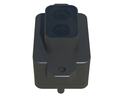
Mechanical assembly involves mounting the laser and coil in a rigid, aligned housing. Use adjustable brackets to fine-tune the laser's path, ensuring the beam intersects precisely with the inductive field. Thermal management is often overlooked; incorporate heat sinks for the laser driver and oscillator components to maintain performance over extended periods. Testing should be conducted with various target materials (e.g., steel, aluminum) and surface finishes to validate consistency. Environmental factors like ambient light or dust can affect performance, so consider adding optical filters or protective covers.
In industrial settings, these sensors excel in tasks such as position verification, part counting, or edge detection. Their hybrid design offers advantages over standalone optical or inductive sensors: the laser provides visual alignment cues, while the inductive element ensures immunity to non-metallic obstructions. Future enhancements could include integrating smart features like self-diagnostics or adaptive sensing ranges via programmable logic. By mastering this build, engineers gain deeper insight into sensor fusion technologies, paving the way for innovative solutions in automation. Remember to adhere to laser safety standards (e.g., IEC 60825) and validate the system under real operating conditions before deployment.
