In industrial automation and control system design, the accurate representation of components through standardized electrical symbols is paramount. Among these, the inductive proximity sensor holds a critical role for non-contact detection of metallic objects. Understanding its schematic representation is essential for engineers, technicians, and anyone involved in reading or creating electrical diagrams.
The core function of an inductive proximity sensor is to generate an electromagnetic field from its sensing face. When a metallic target enters this field, eddy currents are induced within the target, causing a change in the sensor's internal oscillation circuit. This change is detected and converted into a switching signal. In electrical schematics, this complex functionality is distilled into a simple, universal symbol to convey its electrical behavior and connections clearly.
The standard electrical symbol for a basic two-wire AC or DC inductive proximity sensor resembles a simple switch symbol enclosed within a circle or a diamond shape, often with the letters 'Ls' or 'Sn' nearby to denote its sensing nature. However, the most informative representation breaks down the sensor into its logical components. Typically, it is depicted as a coil symbol (representing the oscillator coil) adjacent to a semiconductor switching element (like a transistor symbol) inside a circle. The circle universally indicates that the component is a sensor or a device with an integrated function, as opposed to a basic passive component.
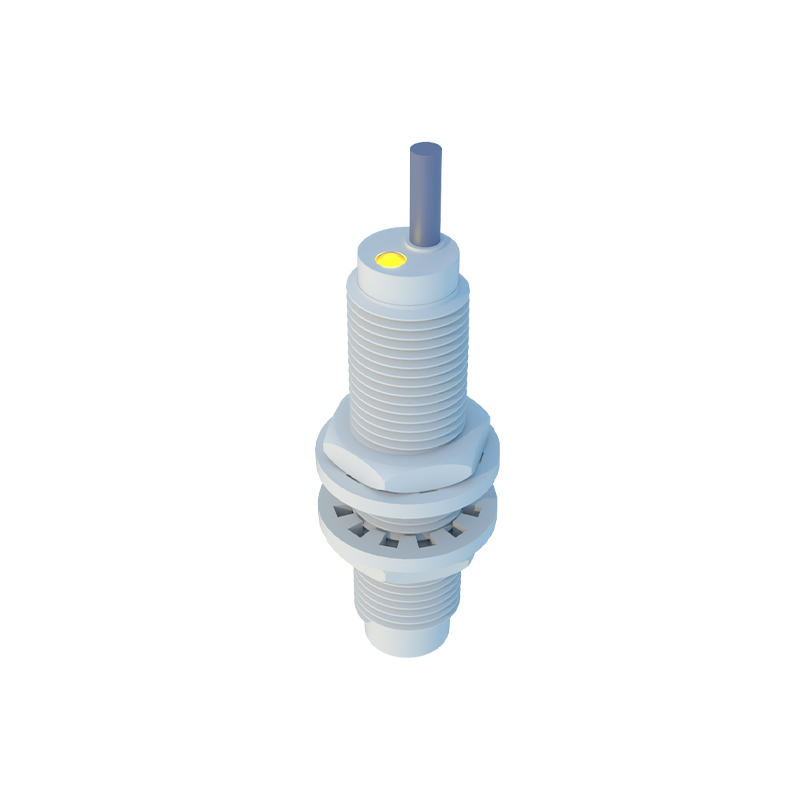
For three-wire and four-wire sensors, which are more common due to their separate power supply and output lines, the symbol becomes more detailed. A standard three-wire NPN (sinking) sensor symbol shows: a circle; inside, a coil on the left connected to the power terminals; and an NPN transistor symbol on the right, its emitter tied to the negative/0V line and the collector forming the switched output. The PNP (sourcing) version flips the transistor symbol accordingly. The three (or four) connection points are clearly labeled: +V (brown wire typically), 0V (blue), Output (black), and sometimes a separate output for a complementary signal (white).
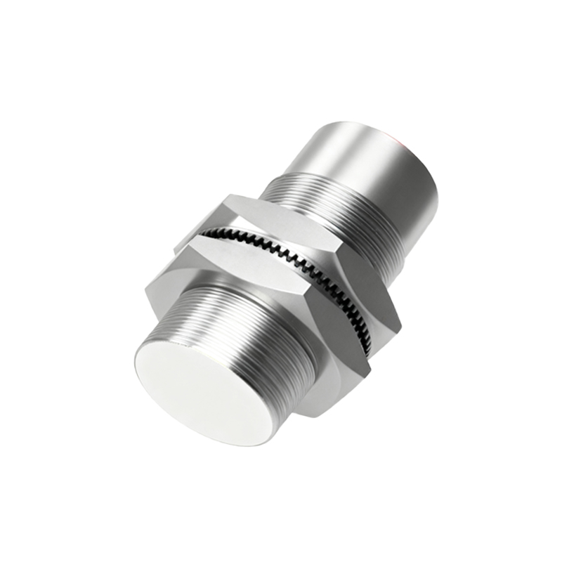
It is crucial to distinguish between Normally Open (NO) and Normally Closed (NC) output configurations in the symbol. A NO symbol shows the output switch as open when no target is present. The NC symbol shows the switch as closed in the same state. This is often indicated by the orientation of the switch contact in the transistor diagram or with a small annotation like "NO" or "NC" near the output line.
Furthermore, advanced sensors with analog current (4-20mA) or voltage (0-10V) outputs, or those with IO-Link digital communication, use modified symbols. An analog output might be shown as a circle with a current source or a potentiometer symbol inside. An IO-Link device symbol often incorporates the standard sensor circle with the letters "IO-L" or a specific communication bus symbol integrated, indicating its smart capabilities beyond simple switching.
When integrating the symbol into a ladder logic diagram, the focus is on its function as an input to a PLC. Here, it is often represented simply as a contact (again, NO or NC) with a unique address label (e.g., I0.0), while the detailed power connections are shown on a separate power distribution diagram. This hierarchical representation is key to clear documentation.
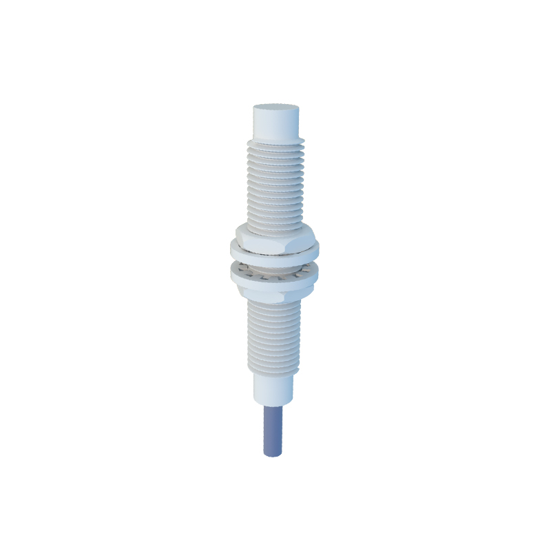
Misinterpreting these symbols can lead to wiring errors, incorrect PLC programming, and system failures. For instance, confusing a PNP symbol with an NPN one will result in a non-functional circuit if connected to a PLC input card of the opposite type. Therefore, always cross-reference the symbol on the schematic with the manufacturer's datasheet for the specific model, paying close attention to the terminal designations (1, 2, 3 / +, -, OUT) and the output type.
In conclusion, the electrical symbols for inductive proximity sensors are a concise graphical language. They abstract the physical device into its essential electrical form, showing power requirements, output type (digital/analog, NO/NC, PNP/NPN), and logical function. Mastery of these symbols is not merely an academic exercise but a fundamental skill for designing, troubleshooting, and maintaining robust and efficient automated electrical systems. Always remember that the circle encapsulates the intelligence of the device, and the internal details tell you exactly how it interfaces with the rest of your control world.