Proximity sensors are fundamental components in modern industrial automation, enabling non-contact detection of objects within a specific range. This animated explanation delves into the core working principles of various proximity sensor types, providing a clear visual and technical understanding for engineers and technicians.
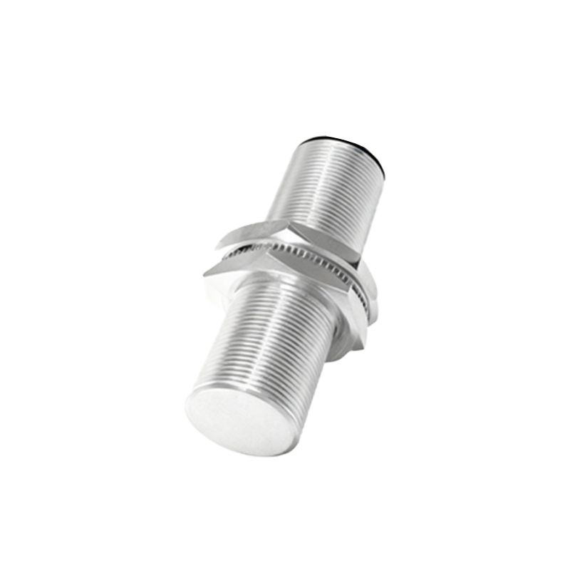
The most common type is the inductive proximity sensor. Its operation relies on electromagnetic induction. Internally, the sensor contains an oscillator circuit that generates a high-frequency alternating magnetic field from a coil wound around a ferrite core. This field emanates from the active face of the sensor. When a metallic target enters this electromagnetic field, eddy currents are induced on the surface of the target. These eddy currents draw energy from the oscillator, causing a reduction in its oscillation amplitude. A dedicated evaluation circuit continuously monitors this amplitude. Once the amplitude drop exceeds a predefined threshold—signifying the target is within the nominal sensing range—the circuit triggers a change in the sensor's output state (e.g., from OFF to ON). The animation effectively illustrates how the magnetic field distortion and energy loss correlate with target proximity, highlighting factors like sensing distance and the influence of different metals (ferrous vs. non-ferrous) on performance.
Capacitive proximity sensors function on a different principle: the change in capacitance. The sensor's active face acts as one plate of a capacitor, with the target object acting as the other plate, and the air gap as the dielectric. The sensor's internal oscillator is tuned to a specific capacitance value. As a target (metal, plastic, liquid, powder, etc.) approaches the active face, it alters the dielectric constant of the space between, thereby increasing the overall capacitance. When this capacitance reaches the trigger point of the oscillation circuit, the output state switches. The animation demonstrates this by showing the electric field lines extending from the sensor face and how different material dielectrics affect the field, enabling the detection of non-metallic objects that inductive sensors cannot sense.
Ultrasonic proximity sensors utilize sound waves. They contain a transducer that emits high-frequency ultrasonic pulses (typically beyond 20 kHz). These pulses travel through the air, reflect off a target object, and return to the sensor as an echo. An internal electronic timer measures the time interval between pulse emission and echo reception. Since the speed of sound in air is constant under known conditions, the sensor's control circuitry calculates the distance to the target using the formula: Distance = (Speed of Sound × Time of Flight) / 2. The output is switched when the calculated distance falls below the set threshold. The animation visualizes the sound wave propagation, reflection, and the critical time-of-flight measurement, explaining concepts like blind zone and beam angle.
Photoelectric sensors, often used for longer-range proximity detection, operate by emitting a beam of light (visible, infrared, or laser) from a transmitter. A receiver detects the light. In the opposed (through-beam) mode, detection occurs when an object interrupts the beam between separate transmitter and receiver units. In the diffuse (reflective) mode, the sensor's receiver detects light reflected directly from the target. A specialized version, the retro-reflective mode, uses a reflector to bounce the beam back. The animation clarifies these modes, showing the light path interruption or reflection as the detection mechanism. It also explains how background suppression and foreground suppression techniques work in diffuse sensors to ignore objects beyond or before a set distance.
Each sensor type has distinct advantages. Inductive sensors are robust, precise for metals, and immune to environmental factors like dust or moisture affecting detection. Capacitive sensors offer versatility for various materials but can be influenced by humidity or temperature changes. Ultrasonic sensors excel at detecting objects regardless of color or transparency and work well in challenging environments but are slower and sensitive to temperature and air turbulence. Photoelectric sensors provide long ranges and fast response but can be affected by ambient light, dirt on lenses, or highly reflective targets.
Understanding these animated principles is crucial for proper sensor selection. Key selection criteria include: the nature of the target material (metal, plastic, liquid), required sensing distance, environmental conditions (presence of dust, oil, temperature extremes), response speed, output type (PNP/NPN, analog, IO-Link), and installation constraints. A well-chosen sensor, based on a solid grasp of its working principle, ensures reliability, reduces downtime, and optimizes automated system performance. This knowledge empowers engineers to troubleshoot issues effectively, such as understanding why a sensor might trigger erratically (due to metal shavings for an inductive sensor or acoustic noise for an ultrasonic sensor) or fail to detect a transparent object with a standard photoelectric beam.