In industrial automation and machinery, proximity sensors are indispensable components that enable non-contact detection of metallic or non-metallic objects. However, a common and frustrating issue encountered by engineers and maintenance personnel is when a proximity sensor fails to read or detect a target object. This malfunction can lead to production halts, safety risks, and costly downtime. Understanding the root causes and systematic troubleshooting methods is crucial for maintaining operational efficiency.
Firstly, it is essential to recognize the primary types of proximity sensors: inductive, capacitive, and photoelectric. Inductive sensors detect metallic objects, capacitive sensors detect both metallic and non-metallic materials, and photoelectric sensors use light beams. Each type has specific operational principles and failure modes. A sensor "not reading" typically means it does not change its output state when a target enters its sensing range.
One of the most frequent causes is incorrect installation or mounting. The sensing distance specified in datasheets is usually under ideal conditions. In real-world applications, factors like the target material, size, and approach angle can significantly reduce the effective sensing range. For inductive sensors, if a non-ferrous metal like aluminum or copper is used instead of steel, the sensing distance may drop by up to 60%. Similarly, capacitive sensors can be affected by environmental humidity or contamination on the sensing face. Ensuring the target is within the corrected sensing range and approaches the sensor head correctly is the first checkpoint.
Electrical issues constitute another major category. Voltage supply problems are common. A proximity sensor requires a stable power supply within its rated voltage range (e.g., 10-30V DC). Voltage spikes, drops, or excessive ripple can cause erratic behavior or complete failure. Always verify the supply voltage at the sensor's terminals using a multimeter under load. Wiring errors are equally prevalent. Incorrectly connecting the load (like a PLC input) in series or parallel, swapping Brown (positive), Blue (negative), and Black (output) wires, or having loose connections can prevent proper operation. For 3-wire sensors, ensuring the correct sinking (NPN) or sourcing (PNP) configuration matches the control system is vital. A mismatch will result in no signal.
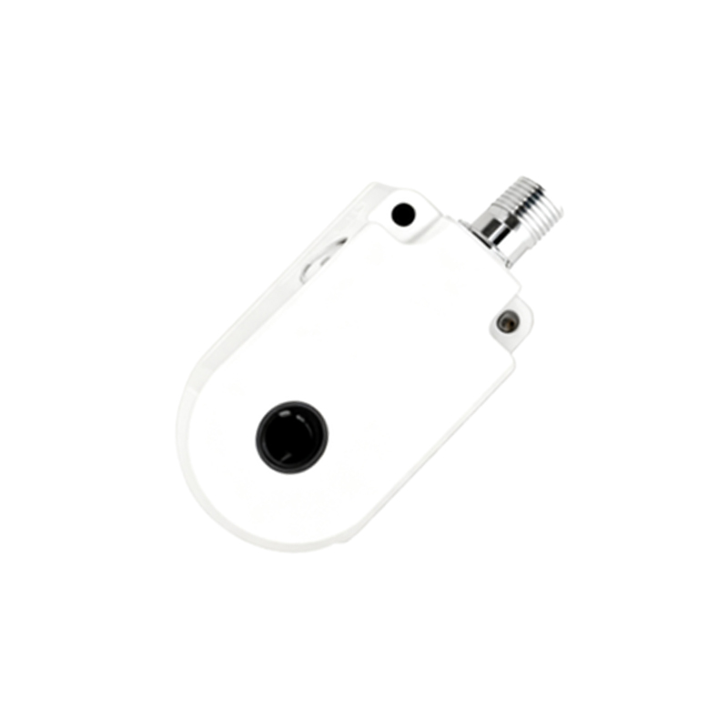
Environmental interference is a stealthy culprit. Inductive sensors can be influenced by strong electromagnetic fields from nearby motors, transformers, or welding equipment. This interference can cause false triggering or desensitization. Electrically isolating the sensor or using shielded cables can mitigate this. For capacitive sensors, changes in the surrounding dielectric—such as moisture, dust, or other materials close to the sensor—can alter its sensitivity, causing it to trigger prematurely or not at all. Photoelectric sensors are highly susceptible to ambient light interference (like sunlight or strobe lights) or obstructions like dust and fog on the lenses.
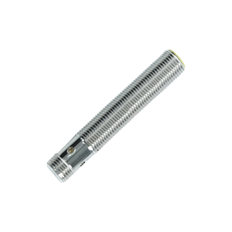
Sensor degradation and physical damage over time are inevitable. The oscillator coil in inductive sensors can degrade. The sensing face might accumulate metal shavings, oil, paint, or other debris, forming a barrier that attenuates the electromagnetic field. A simple cleaning with a soft cloth and isopropyl alcohol can often restore function. Physical damage from impacts, vibration, or excessive temperature beyond the sensor's specification can also lead to internal component failure. Always check the sensor's housing for cracks and the cable for wear or cuts.
A structured troubleshooting approach is recommended. Begin with a visual inspection: check for physical damage, contamination, and verify correct target positioning. Next, perform electrical checks: measure the supply voltage, inspect wiring integrity and correctness, and use an oscilloscope to check for noise on the signal line if possible. Then, test the sensor independently: if feasible, temporarily replace it with a known-good sensor of the same model. Monitor the output LED indicator (if present) to see if it activates when the target is presented. Finally, consult the sensor's manual to verify its specifications, including sensing distance, target material, temperature ratings, and output type.
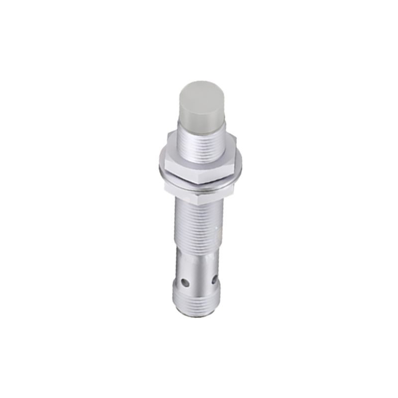
In conclusion, a proximity sensor failing to read is rarely a random event. It is typically a symptom of identifiable issues related to installation, electrical supply, environmental conditions, or sensor health. By applying a logical, step-by-step diagnostic process, maintenance teams can quickly isolate the cause—whether it lies with the sensor itself, the target, the wiring, or the environment—and implement an effective solution, thereby minimizing disruption and ensuring the reliability of the automated system.