Laser proximity sensors are pivotal components in modern industrial automation, offering high precision and reliability for object detection and distance measurement. Understanding their wiring principles is essential for ensuring optimal performance and system integration. This article delves into the core wiring concepts, common configurations, and best practices for laser proximity sensors in industrial applications.
At the heart of a laser proximity sensor lies its ability to emit a focused laser beam and detect the reflected light from a target object. The wiring of these sensors typically involves connecting power supply lines, output signals, and, in some cases, communication interfaces. Most industrial laser proximity sensors operate on DC voltages, commonly 12-24V DC, to ensure stable operation in harsh environments. The power wiring must adhere to strict polarity guidelines: the positive terminal (often labeled V+ or brown wire) connects to the positive supply, while the negative terminal (labeled V- or blue wire) links to the ground. Incorrect polarity can lead to sensor damage or malfunction, so verifying the manufacturer's datasheet is crucial before installation.
Output wiring varies based on the sensor type and application requirements. Laser proximity sensors generally provide digital outputs, such as NPN (sinking) or PNP (sourcing) transistor configurations, to interface with programmable logic controllers (PLCs) or other control systems. In an NPN setup, the output wire (usually black) switches the load to ground when the sensor detects an object, making it suitable for common-negative systems. Conversely, PNP sensors switch the positive supply to the load, aligning with common-positive systems. Selecting the correct output type depends on the control system's design; mismatching can cause compatibility issues. Some advanced models also feature analog outputs (e.g., 0-10V or 4-20mA) for continuous distance measurement, requiring additional wiring for signal transmission to analog input modules.
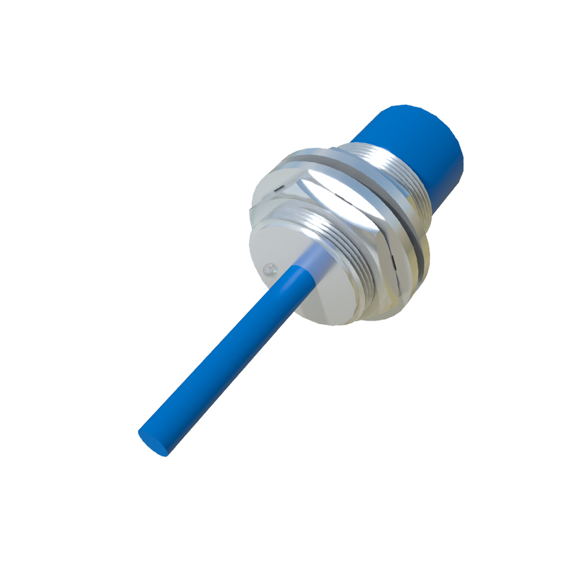
For enhanced functionality, many laser proximity sensors include auxiliary connections, such as teach-in wires for setting detection thresholds or IO-Link communication for real-time data exchange. Wiring these features involves connecting dedicated pins to control devices, enabling remote configuration and diagnostics. In industrial setups, proper cable management is vital to prevent electromagnetic interference (EMI) from affecting sensor accuracy. Shielded cables are recommended, with the shield grounded at one end to minimize noise. Additionally, sensors should be wired away from high-voltage lines and motors to avoid signal degradation.
Safety considerations are paramount when wiring laser proximity sensors. Always disconnect power before making connections to prevent electrical hazards. Use appropriate wire gauges as per current ratings, and secure terminals with crimp connectors or screw clamps to ensure reliable contact. For environments with vibration or movement, strain relief mechanisms should be employed to protect wiring from fatigue. Regular testing with a multimeter can verify voltage levels and output signals, aiding in troubleshooting issues like false triggers or no response.
In summary, mastering the wiring principles of laser proximity sensors involves understanding power requirements, output types, and integration techniques. By following manufacturer guidelines and industry standards, engineers can deploy these sensors effectively in applications ranging from robotics to quality control, enhancing automation efficiency and precision. As technology evolves, features like smart wiring with plug-and-play connectors are simplifying installations, but the fundamentals of correct electrical connections remain key to long-term reliability.