Accurate and reliable weld seam tracking is critical for achieving high-quality, consistent results in automated welding applications. The laser weld seam tracking sensor has become an indispensable tool in modern manufacturing, enabling real-time correction of robot or torch path to compensate for part fit-up variations, thermal distortion, and fixture inaccuracies. However, the full potential of this technology is only realized through meticulous installation. A poorly installed sensor can lead to inaccurate readings, system errors, and ultimately, defective welds. This guide provides a comprehensive, step-by-step approach to installing a laser seam tracking sensor, ensuring it delivers precise data for flawless welding operations.
The foundation of a successful installation is pre-installation planning. Before mounting any hardware, thoroughly review the sensor manufacturer's technical documentation. Identify the specific model's requirements for mounting orientation, working distance, field of view, and environmental protection (IP rating). Crucially, assess the welding environment. Factors such as intense arc glare, spatter, smoke, and electromagnetic interference from welding power sources can severely impact sensor performance. Plan the sensor's location to minimize exposure to these elements. Often, this involves mounting the sensor ahead of the welding torch in the travel direction, with a slight offset to keep it out of the direct plume of smoke and spatter. Ensure the chosen mounting location on the robot arm or carriage is rigid and vibration-free, as mechanical shock and vibration can damage the sensitive laser and camera components.
The physical mounting process demands precision. Most sensors are mounted using a dedicated bracket supplied by the manufacturer or integrator. Securely fasten this bracket to the robot's sixth axis, torch mounting plate, or a custom fixture. Use high-grade fasteners and apply appropriate torque to prevent loosening during operation. When attaching the sensor to the bracket, pay close attention to the specified stand-off distance—the precise gap required between the sensor head and the workpiece surface. This distance is paramount; even a few millimeters of deviation can blur the laser line or alter its measurement perspective, causing tracking errors. Many sensors have a mounting flange with adjustment slots. Tighten these bolts only enough to hold the sensor while allowing for final fine-tuning.
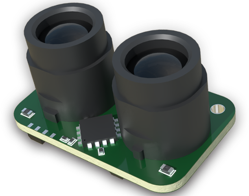
Sensor alignment is the most critical step for functional accuracy. The sensor must be positioned so that its laser stripe projects perpendicularly onto the joint preparation (e.g., V-gap, lap, fillet) ahead of the welding arc. The camera must have a clear, unobstructed view of this laser line. Begin with coarse alignment using visual indicators. Power on the sensor (without initiating the welding arc) and observe the projected laser line on a test workpiece. Use the bracket's adjustment mechanisms to center the laser line perfectly on the joint seam. Next, perform fine alignment using the sensor's software interface. Connect the sensor to the tracking system's processor and open the configuration software. The interface will typically display a live video feed from the sensor's camera. Precisely adjust the sensor's pitch, yaw, and roll until the laser line appears sharp, straight, and correctly positioned within the software's defined "window of interest." The software will often provide numeric feedback on alignment quality. Secure all adjustment bolts firmly once optimal alignment is achieved.
Following mechanical installation, integrate the sensor with the control system. This involves connecting three main components: power, data, and I/O cables. Route the sensor's power cable to a clean, stable power supply as specified in the manual, often 24V DC. Protect data cables (typically Ethernet-based, like EtherCAT or Profinet) from interference by running them separately from high-power welding cables and motor leads. Use shielded conduits whenever possible. Connect the sensor's digital I/O cables to the robot controller or programmable logic controller (PLC) to enable functions like "Tracking On/Off" or error signaling. Proper grounding is essential; connect the sensor's ground terminal to the central grounding point of the welding system to avoid ground loops and electrical noise.
Before commencing production, execute a rigorous calibration and validation procedure. Calibration translates the camera's pixel data into real-world measurements. The process usually involves moving the sensor over a calibration plate with known geometric features. The system software learns the spatial relationship between the sensor and the torch tip (TCP). This step is non-negotiable for accuracy. After calibration, run a series of test welds on sample parts with known joint variations. Monitor the sensor's feedback in the software—it should accurately report the seam's position, gap, and mismatch in real-time. Verify that the welding torch correctly follows the joint path as commanded by the tracker. Inspect the final weld bead for consistency. Document all parameters, including mounting position, alignment values, and calibration data, for future reference and quick troubleshooting.

Routine maintenance preserves long-term performance. Establish a daily check to clean the sensor's protective window. A thin layer of spatter or dust can scatter the laser beam. Use recommended cleaning tools, such as a soft brush or lint-free cloth with a suitable solvent. Periodically inspect all cable connections for tightness and signs of wear. Check the mounting hardware for any loosening caused by vibration. Re-validate the calibration weekly or after any significant mechanical impact. By treating the laser seam tracking sensor as a precision optical instrument and adhering to these detailed installation and maintenance protocols, manufacturers can ensure robust, reliable performance that maximizes weld quality, reduces rework, and boosts overall productivity in automated welding cells.