In industrial automation and control systems, the integration of proximity sensors with audible indicators like buzzers is a fundamental yet critical task. This combination provides an immediate, non-visual alert for machine status, object detection, or process completion. As an electrical engineer, understanding the correct interfacing methods is essential for reliable system operation. This guide details the step-by-step process, covering sensor types, circuit considerations, and practical wiring.
First, identify the specifications of your components. Proximity sensors primarily come in two output types relevant for driving a buzzer: NPN (sinking) and PNP (sourcing). An NPN sensor switches the negative (ground) side of the load, while a PNP sensor switches the positive voltage side. The buzzer must be a DC-operated model, typically available in active (self-oscillating with a fixed tone) or passive (requires an external oscillating signal) types. For simplicity, an active DC buzzer is recommended. Check the voltage ratings; a common setup uses a 24VDC sensor and a 24VDC buzzer, though 12VDC systems are also prevalent.
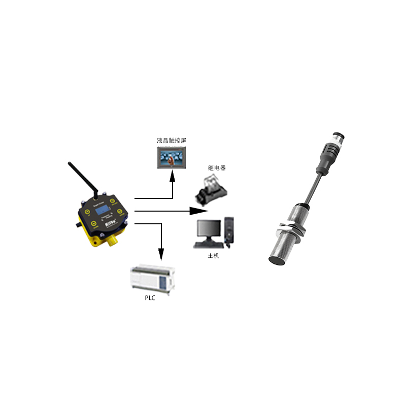
The core principle is to treat the sensor's output as a switch that controls power to the buzzer. Let's examine the wiring for an NPN sensor configuration. You will need a DC power supply (e.g., 24VDC), the NPN proximity sensor, the buzzer, and possibly a current-limiting resistor if the buzzer's current draw exceeds the sensor's rated switching capacity.
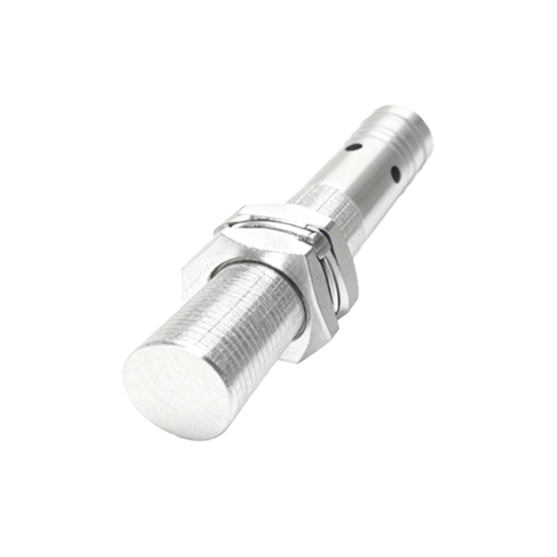
1. Connect the positive terminal (+) of your DC power supply to the sensor's brown wire (typically V+ or supply positive).
2. Connect the negative terminal (-) of the power supply to the sensor's blue wire (typically 0V or common).
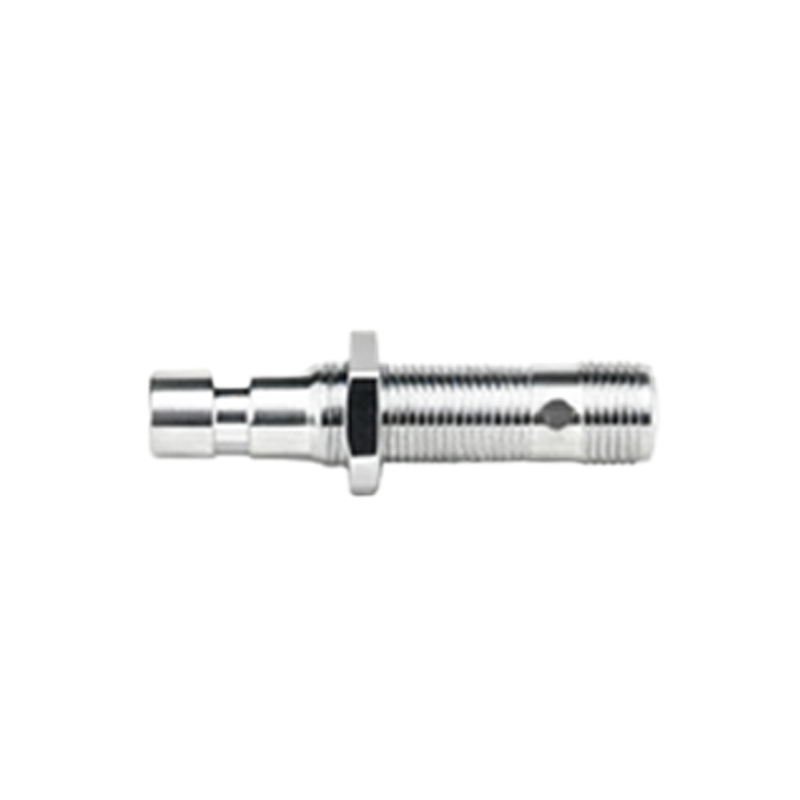
3. The sensor's black wire is the switched NPN output. Connect this wire to the negative terminal of the buzzer.
4. Finally, connect the positive terminal of the buzzer back to the positive terminal (+) of the DC power supply.
This forms a complete circuit: Power (+) -> Sensor (internal circuitry) -> Sensor Output (Black) -> Buzzer (-) -> Buzzer (+) -> back to Power (+). When the sensor detects an object, its internal NPN transistor saturates, connecting the black output wire to the internal ground (blue wire). This closes the circuit, allowing current to flow through the buzzer, activating the sound.
For a PNP sensor configuration, the switching logic is reversed. The sensor's output (usually a black wire) provides positive voltage when active.
1. Connect power supply (+) to the sensor's brown wire.
2. Connect power supply (-) to the sensor's blue wire.
3. Connect the sensor's black (PNP output) wire to the positive terminal of the buzzer.
4. Connect the negative terminal of the buzzer directly to the negative terminal (-) of the DC power supply.
In this circuit, the PNP sensor acts as a sourcing switch, providing power to the buzzer upon detection.
Critical considerations include load compatibility. Always verify the sensor's maximum switching current and voltage against the buzzer's operating requirements. If the buzzer draws 50mA and your sensor is rated for 100mA, it is safe. If the buzzer draws more current, you must add an intermediary relay. Connect the sensor output to drive the relay coil, and use the relay's heavier-duty contacts to switch the buzzer's power circuit. This protects the sensor's fragile solid-state output from damage due to overcurrent.
Another key point is the inclusion of a protection diode, especially when using a relay coil or an inductive buzzer. A flyback diode (like a 1N4007) should be placed in reverse bias across the buzzer/coil terminals (anode to negative, cathode to positive) to suppress voltage spikes generated when the circuit is de-energized.
For testing, apply power. The sensor may have a power-on indicator (LED). Trigger the sensor by bringing a metallic target (for inductive sensors) within its sensing range. The sensor's output indicator should light, and the buzzer should sound immediately. If it does not, double-check all connections with a multimeter. Measure voltage at the buzzer terminals when the sensor is active; you should read the full supply voltage. If voltage is present but the buzzer is silent, the buzzer may be faulty or polarity may be incorrect for some models.
Advanced implementations might involve connecting the sensor to a Programmable Logic Controller (PLC) digital input, and the buzzer to a PLC digital output. This allows for programmed logic, delays, or latching alarms. However, the direct hard-wired method described remains a