Disassembling a proximity switch sensor is a task that may be required for maintenance, repair, or inspection purposes. As a professional in the electrical and automation industry, it is crucial to approach this procedure with the correct methodology, tools, and safety precautions. This guide provides a step-by-step, industry-standard approach to safely taking apart a typical inductive or capacitive proximity sensor.
1. Preliminary Safety and Preparatory Steps
Before any physical work begins, safety is paramount. Always adhere to Lockout-Tagout (LOTO) procedures. Ensure the entire system and the specific circuit containing the proximity sensor are completely de-energized. Verify the absence of voltage using a appropriately rated multimeter. Wear appropriate personal protective equipment (PPE), such as safety glasses and insulated gloves. Gather the necessary tools: typically, a set of precision screwdrivers (flat-head and Phillips), hex keys (Allen wrenches), and possibly a small wrench set. Have a clean, static-free workspace ready.
2. Sensor Removal from Mounting
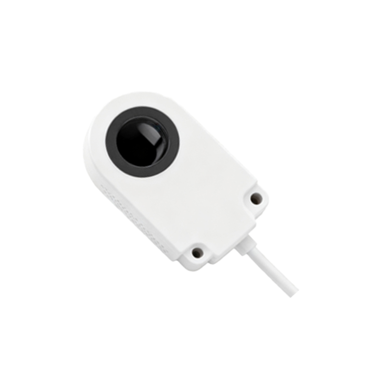
Most proximity sensors are mounted via a threaded barrel (e.g., M8, M12, M18, M30) or with mounting brackets. For threaded types, use the correct size wrench to carefully unscrew the sensor from its mounting hole. Avoid applying excessive force to the sensor housing or the cable entry point, as this can damage internal components. For bracket-mounted sensors, unscrew the fastening bolts or nuts that secure the bracket. Gently disconnect the sensor from its electrical connector or, if hard-wired, you will need to note the wiring scheme before proceeding to the next step.
3. Disconnecting Electrical Connections
If the sensor is connector-based, simply unplug it. For hard-wired sensors, this step must be done with extreme care and accurate documentation. Using a screwdriver, loosen the terminal screws within the sensor's connection head or cable gland. Carefully remove each wire, noting its color, terminal number, and corresponding function (e.g., Brown/+V, Blue/0V, Black/Output). Taking a photograph before disconnection is highly recommended. This documentation is vital for correct reassembly and system restoration.
4. Accessing the Internal Housing
The main housing of a proximity sensor is typically sealed to protect against dust and moisture (IP rated). Access is usually gained by separating the sensing face/head from the body or by opening the connection head compartment. Look for small set screws, plastic clips, or a threaded interface. Some models have a hex socket on the rear. Insert the correct tool and turn counter-clockwise. The housing should begin to separate. If it feels fused due to sealant or environmental factors, apply gentle, even prying force. Never use excessive force or sharp tools that can crack the housing or damage sealing surfaces.
5. Core Component Disassembly
Once the housing is open, you will see the internal assembly. This generally consists of the oscillator coil, amplifier circuit board, and output switching component (transistor). The components are often potted in epoxy or silicone for protection. Important Note: If the sensor is potted, disassembly for component-level repair is usually impractical and not recommended by manufacturers; the unit is typically considered non-serviceable at this stage. The purpose of opening it then is primarily for inspection of external damage or cleaning.
For non-potted or partially potted units, you may proceed. The circuit board is usually fixed with small screws or plastic posts. Remove these fasteners. Note the orientation of the board and any connectors (e.g., to the coil). Gently lift the board out. The sensing coil is often wound around a ferrite core and may be removable. Handle the coil and circuit board with care to avoid static discharge (use an ESD strap if available).
6. Inspection and Cleaning
With the components exposed, inspect for visible signs of failure: burnt components on the PCB, cracked solder joints, corrosion on terminals, physical damage to the coil, or broken wires. The sensing face should be clean of metallic swarf or other contaminants. Use compressed air or a soft brush for cleaning. Do not use solvents on the coil or PCB unless specified by the manufacturer.
7. Reassembly Considerations
Reassembly is essentially the reverse process. Ensure all seals and O-rings are intact and properly seated in their grooves. If a seal is damaged, it must be replaced to maintain the IP rating. Carefully reposition the circuit board and coil, securing all screws firmly but without over-tightening. Before closing the main housing, it is good practice to perform a basic functional test if possible (by temporarily connecting power in a safe, controlled environment). Finally, screw the housing parts together evenly to ensure a proper seal. Reconnect the wiring exactly as documented.
Conclusion
Successful disassembly