In the realm of industrial automation and electrical engineering, laser sensors play a pivotal role in precision measurement, object detection, and quality control. Their representation in electrical schematics through standardized symbols is crucial for clear communication among engineers, technicians, and designers. This article delves into the common laser sensor symbols, their components, and interpretation within circuit diagrams, adhering to international standards like IEC 60617.
A typical laser sensor symbol in a schematic is not a single icon but a combination of graphical elements that convey its function. The core component often resembles a standard photoelectric sensor symbol, which is a circle or a square with a built-in light source and receiver indicators. To specifically denote a laser, a distinct wavy or straight arrow line, sometimes labeled with "LASER," emanates from the sensor body, representing the emitted coherent light beam. The receiver side is usually shown with a similar but receiving arrow or a photodiode symbol. For example, a retro-reflective laser sensor symbol might show the transmitter and receiver within one housing, with the arrow pointing outward to a separate reflector symbol (often a small rectangle with a diagonal line). A through-beam sensor would be represented by two separate symbols: a transmitter and a receiver unit placed opposite each other in the diagram.
The symbol also incorporates electrical connection points. These are typically represented by small lines or terminals on the sensor body, connecting to the power supply (usually marked as +V and 0V or COM) and the output signal line. The output type (PNP/NPN, analog, or digital) is often indicated by the internal marking of the symbol or in accompanying documentation. For instance, a switch inside the circle might denote a digital output. It is essential to cross-reference the symbol with the manufacturer's datasheet, as variations can exist.
Understanding these symbols requires knowledge of the sensor's operating principle. The laser emits a focused beam; when this beam is interrupted or reflected by an object, the receiver detects the change, and the sensor's internal circuitry triggers an output. The schematic symbol abstracts this physical process into a logical electrical function. Additional symbols might be included for adjustable sensitivity, timing functions, or alignment indicators, often shown as small potentiometers or clock icons adjacent to the main symbol.
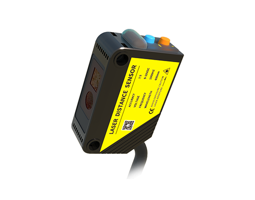
Correct interpretation prevents wiring errors and ensures system integrity. Misreading a PNP output symbol as an NPN, for instance, could lead to incorrect PLC input module selection. Therefore, engineers must be proficient in these symbols to design, troubleshoot, and maintain automated systems efficiently. Always consult the specific project's legend sheet for any unique symbol variations.
In summary, laser sensor symbols are a standardized graphical language that encapsulates the device's functionality within an electrical circuit. Mastery of these symbols, combined with practical knowledge of laser sensor applications—from packaging machinery to robotic guidance—is fundamental for any professional in the electrical and automation fields. Clear schematics with accurate symbols enhance safety, reduce downtime, and facilitate global collaboration on technical projects.