In industrial automation and precision measurement, laser sensor amplifiers play a critical role in converting weak optical signals into reliable, processable electrical outputs. Proper adjustment of these amplifiers is essential to ensure accuracy, stability, and longevity of the entire sensing system. This guide provides a step-by-step approach to tuning laser sensor amplifiers, tailored for engineers and technicians in the electrical and automation fields.
First, understand the basic components: a laser sensor system typically includes a laser emitter, a receiver, and an amplifier. The amplifier’s primary function is to amplify the receiver’s signal to a level suitable for control systems or data acquisition devices. Key parameters involved in adjustment include gain, threshold, response time, and output type (e.g., analog or digital).
Begin with system preparation. Ensure the laser sensor and amplifier are correctly wired according to the manufacturer’s specifications. Power on the system and allow it to stabilize for a few minutes, as temperature variations can affect initial performance. Verify that the laser beam is properly aligned with the target and receiver; misalignment is a common source of signal weakness or noise.
Next, focus on gain adjustment. Gain controls the amplification level of the input signal. Start with a low gain setting to avoid saturation or distortion. Gradually increase the gain while observing the output on an oscilloscope or monitoring software. The goal is to achieve a clear, stable signal without excessive noise. If the signal peaks or clips, reduce the gain slightly. In environments with high ambient light or interference, consider using filters or shielding to improve signal integrity.
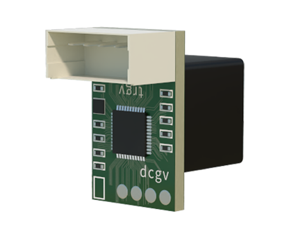
Threshold setting is crucial for digital outputs. The threshold determines the signal level at which the amplifier triggers an output change (e.g., from LOW to HIGH). Adjust the threshold based on the application requirements. For object detection, set it just above the noise floor but below the signal strength when the target is present. Test by moving the target in and out of the beam; the output should switch consistently without false triggers. Use hysteresis if available to prevent chatter in borderline conditions.
Response time adjustment balances speed and stability. A faster response time is needed for high-speed applications but may increase susceptibility to noise. Slower response times smooth out fluctuations but can delay detection. Match this setting to the dynamics of your process. For instance, in conveyor belt sorting, a medium response time might be optimal to handle varying object speeds without missing items.
Calibrate the output type accordingly. If using analog output (e.g., 4-20 mA or 0-10 V), ensure it corresponds linearly to the measured distance or intensity. Perform a two-point calibration: set the output at a known minimum and maximum signal level. For digital outputs, verify the switching logic (normally open or closed) aligns with the control system’s expectations.
Environmental factors must not be overlooked. Temperature, humidity, and vibration can impact amplifier performance. Install the amplifier in a controlled enclosure if operating in harsh conditions. Regularly check for dust or condensation on optical components, as these can attenuate the laser signal.
Finally, document all settings and conduct periodic maintenance. Record the gain, threshold, and response time values for future reference. Schedule routine checks to recalibrate as needed, especially after system modifications or environmental changes.
By following these steps, engineers can optimize laser sensor amplifiers for reliable operation, reducing downtime and enhancing measurement precision in applications ranging from manufacturing to robotics.