Drawing accurate and standardized proximity sensor schematics is a fundamental skill for electrical engineers working in automation, industrial control, and system design. A well-drawn schematic serves as a universal language, ensuring clear communication between design, installation, and maintenance teams. This guide provides a step-by-step professional approach to creating these essential diagrams, adhering to common international standards like IEC and ANSI/IEEE.
The first step is understanding the sensor type. Proximity sensors are broadly categorized by their operating principle: inductive, capacitive, ultrasonic, or photoelectric. Each type has a distinct schematic symbol. Inductive sensors, detecting metallic objects, are often represented by a coil symbol within a square or diamond shape, sometimes with a sine wave icon. Capacitive sensors, for both metallic and non-metallic materials, may include a capacitor-like symbol. Photoelectric sensors typically integrate an LED (transmitter) and a phototransistor (receiver) in their icon. Always refer to the specific manufacturer's datasheet for the recommended symbol, as variations exist.
Before drawing, gather all necessary information: the sensor's part number, power supply requirements (e.g., 10-30V DC, PNP vs. NPN output type), output configuration (normally open/NO or normally closed/NC), and connection points. A typical three-wire DC sensor will have connections for Brown (V+), Blue (V- or common), and Black (output signal). For four-wire sensors, a second output wire (often White) is present.
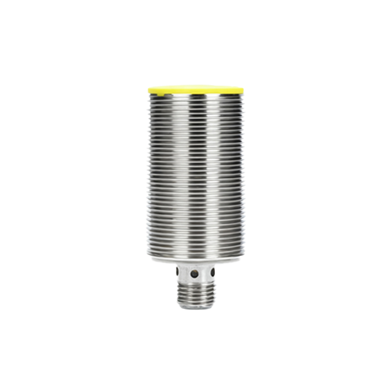
Start your schematic in dedicated CAD software like EPLAN, AutoCAD Electrical, or even precise vector graphic tools. Begin by placing the sensor symbol. The symbol should be clear and uncluttered. Next, draw the power supply circuit. Connect the positive supply line (e.g., +24VDC) to the sensor's positive terminal (Brown wire). Connect the negative supply line (0VDC or common) to the sensor's negative terminal (Blue wire). It is crucial to include a fuse or circuit breaker in the positive supply line for protection. Label all voltages.
The output circuit is critical. For a PNP (sourcing) sensor, the Black output wire provides a positive voltage when activated. This wire is connected to the load (e.g., a PLC input module, relay coil). The other side of the load is then connected to the common negative (0VDC). For an NPN (sinking) sensor, the Black output wire connects to the load, and the other side of the load connects to positive voltage; the output sinks current to common. Always draw the load (like a PLC input, symbolized as a rectangle with an "I" or specific tag) and clearly indicate the connection. Use a dashed line or a separate box to represent the sensing field or target area.
Wiring details must be explicit. Use distinct line styles for different voltage levels. Include wire numbers, terminal numbers, and cable designations consistent with your overall project's wiring diagram. Add text annotations for the sensor's model, sensing range, and setpoint if applicable. For example, annotate near the symbol: "IE-5008, Inductive, 8mm, PNP NO."
For complex systems with multiple sensors, maintain consistency in symbol use and layout. Group sensors by function or location on different sheets of the drawing, using cross-references. Always include a legend or symbol list on the first sheet explaining all icons and abbreviations used.
Finally, review the schematic for errors. Check for short circuits, incorrect output types relative to the load, missing protective devices, and proper grounding symbols. Ensure the drawing follows your company's or project's specific drafting standards. A technically precise schematic not only facilitates correct installation but also drastically reduces troubleshooting time, ensuring system reliability and safety. Remember, the goal is to create a drawing that any qualified technician can interpret correctly without needing additional documentation.