Proximity sensors are indispensable components in modern industrial automation, manufacturing lines, and various electronic devices. They detect the presence or absence of an object without physical contact, relying on electromagnetic fields, light, or sound. When these sensors malfunction, it can lead to production downtime, safety hazards, and costly repairs. Understanding how to systematically diagnose and resolve proximity sensor issues is a critical skill for maintenance engineers and technicians. This guide outlines a practical, step-by-step approach to troubleshooting common proximity sensor problems.
The first and most crucial step is to accurately identify the symptoms of the failure. Common indicators include the sensor failing to detect a target that is within its specified sensing range, intermittently triggering without a target present, or providing no output signal at all. Before dismantling any equipment, always consult the machine's documentation and follow established lockout/tagout (LOTO) procedures to ensure personal safety and prevent accidental machine startup.
Begin with a visual inspection. Check for obvious physical damage to the sensor housing, lens, or sensing face. Look for cracks, dents, or signs of impact. Inspect the surrounding area for accumulated dirt, metal shavings, coolant, oil, or other contaminants that could coat the sensor face and interfere with its operation. Clean the sensor face carefully with a soft, lint-free cloth and an appropriate cleaner, ensuring it is completely dry before retesting. Simultaneously, examine the sensor's mounting. Vibration or mechanical shock can loosen mounting hardware, causing the sensor to shift out of alignment. Ensure it is securely fastened and correctly positioned relative to the target's path.
Next, verify the electrical connections. Loose, corroded, or damaged wiring is a leading cause of sensor failure. Power down the system and inspect the cable, connector, and terminal blocks. Look for frayed wires, pinched cables, or loose terminal screws. Use a multimeter to check for continuity in the cable and to verify that the correct supply voltage (e.g., 10-30 VDC for many industrial sensors) is present at the sensor's terminals when powered. A significant voltage drop could indicate a problem with the power supply or wiring.
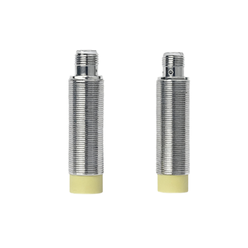
After confirming power and connections, test the sensor's output. The method depends on the output type (PNP/NPN, NO/NC). For a digital sensor, you can use a multimeter set to measure DC voltage. With the sensor powered and a target presented within its sensing range, measure the voltage between the output wire and the common (negative) terminal. Compare the reading to the expected state (e.g., ~24V for a "high" PNP output, ~0V for a "low" NPN output). For analog sensors, observe the output signal change proportionally as the target distance varies. An oscilloscope can be helpful for diagnosing noisy or unstable signals.
Environmental factors are a frequent culprit. Ensure the sensor is suitable for its operating environment. Inductive sensors can be affected by nearby metals other than the target. Capacitive sensors might be triggered by humidity or different materials. Ultrasonic sensors can be disrupted by air turbulence or temperature gradients. Review the sensor's datasheet for specifications regarding temperature limits, environmental protection (IP rating), and electromagnetic compatibility (EMC). Radio frequency interference (RFI) from nearby variable frequency drives (VFDs), welders, or radio transmitters can also cause erratic behavior. Try relocating cables, using shielded cables, or installing ferrite cores.
The target itself must be evaluated. Is it the correct material, size, and shape for the sensor type? An inductive sensor requires a ferrous metal target of adequate size. The target must approach the sensor within its specified sensing distance and from the correct direction. Check for wear or damage on the target object. Also, consider the sensor's operating frequency. If a sensor is cycling too rapidly, it may not have sufficient time to reset between detections, leading to missed signals.
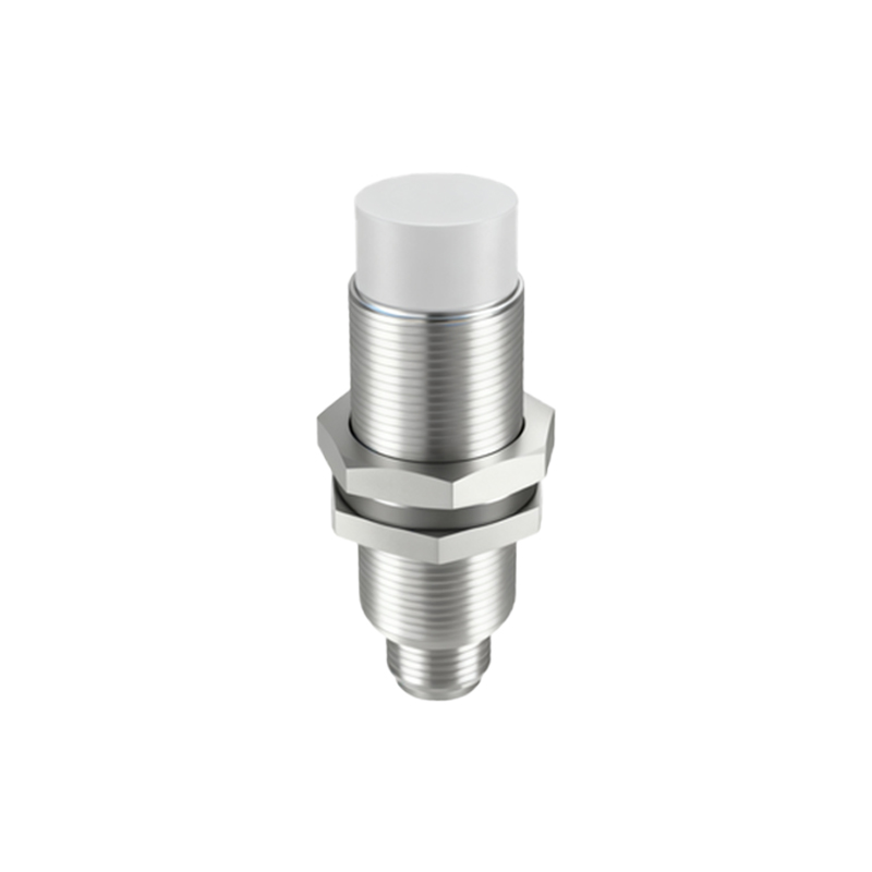
If basic checks yield no results, consult the sensor's diagnostic indicators, if available. Many modern sensors have LED status lights that indicate power (green) and output state (yellow or orange). A solid or blinking pattern can provide specific error codes referenced in the manual. For programmable or intelligent sensors, use configuration software to read parameters, error logs, and real-time diagnostic data.
When a sensor is confirmed faulty after exhaustive testing, replacement is often the most efficient solution. When installing a new sensor, ensure it is an exact match or a approved equivalent, paying close attention to voltage, output type, sensing distance, thread size, and connection style. Calibrate or teach-in the sensor if required, following the manufacturer's instructions. After replacement, perform a full functional test of the system, including multiple cycles under normal operating conditions, to confirm the issue is resolved.
Implementing a proactive maintenance schedule can prevent many failures. This includes