Selecting the appropriate proximity sensor is a critical decision in industrial automation and control system design. The right choice ensures reliability, efficiency, and cost-effectiveness, while a poor selection can lead to system failures, downtime, and increased operational costs. This guide provides a structured approach to proximity sensor selection, focusing on key technical parameters and application-specific considerations.
The first and most fundamental step is to identify the target material. Proximity sensors are primarily categorized by their sensing technology, each suited for different materials. Inductive proximity sensors are designed to detect metallic objects, typically ferrous metals like steel and iron. Their operating principle is based on generating an electromagnetic field; the presence of a metal object within this field induces eddy currents, causing a change in oscillation amplitude that is detected by the sensor. For non-metallic targets—such as plastic, wood, glass, or liquids—capacitive proximity sensors are the standard choice. These sensors detect changes in capacitance caused by the presence of any material that alters the dielectric constant of the space between the sensor's electrode and ground. For long-range detection or for applications requiring sensing of any material regardless of color or transparency, photoelectric sensors (a subtype of proximity sensors) are ideal. Finally, magnetic sensors, often reed switches or Hall-effect sensors, are specifically used to detect permanent magnets.
Once the target material is determined, the next crucial parameter is the sensing distance, often referred to as the "rated operating distance" or "Sn." This is the nominal distance at which the sensor is guaranteed to detect a standard target under specified conditions. It is vital to select a sensor with a sensing distance that provides a sufficient safety margin, typically 10-20% greater than the maximum expected gap between the sensor and the target in the application. This margin compensates for factors like temperature fluctuations, voltage variations, and target material inconsistencies. Do not confuse the rated operating distance with the maximum possible detection distance, which is often less reliable.
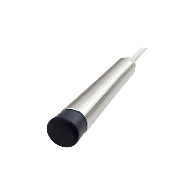
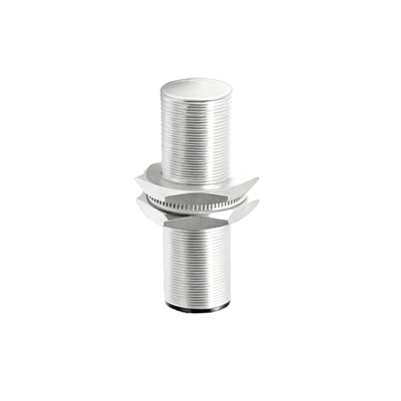
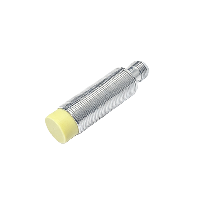
The physical characteristics of the sensor itself are equally important. Consider the housing style: cylindrical sensors (e.g., M8, M12, M18, M30 threaded barrels) are common for general-purpose mounting, while rectangular or block-style sensors may be better for space-constrained environments. The housing material, usually nickel-plated brass, stainless steel, or PBT plastic, must be compatible with the environmental conditions, offering resistance to chemicals, oils, or washdowns if required. The protection rating, denoted by the IP (Ingress Protection) code (e.g., IP67, IP69K), indicates the level of protection against dust and water ingress, which is critical for harsh industrial environments.
Electrical specifications must match the control system. First, determine the required output type: PNP (sourcing) or NPN (sinking) transistor outputs are standard for DC sensors, with PNP being more common in Europe and NPN in some Asian and North American applications. The output configuration can be normally open (NO) or normally closed (NC). The operating voltage range (e.g., 10-30V DC) must be compatible with the available power supply. For AC sensors, standard voltages like 120V or 240V AC are typical. Also, check the load current rating to ensure the sensor can drive the connected load (e.g., a PLC input, relay, or indicator).
Application-specific factors often dictate the final choice. Consider the switching frequency, which is the maximum number of on/off cycles per second the sensor can handle. High-speed applications, such as counting small parts on a fast conveyor, require a high switching frequency. The temperature range of the operating environment must fall within the sensor's specified limits. For mounting, ensure there is adequate clearance around the sensor; inductive sensors, in particular, require non-ferrous mounting brackets and sufficient space from adjacent metal surfaces to prevent false triggering, as specified by the manufacturer's flush-mountable or non-flush-mountable design. Vibration and shock resistance are key for mobile equipment or heavy machinery.
Finally, never overlook installation and wiring practicality. Choose a sensor with a suitable connection type: pre-wired cables, quick-disconnect connectors, or terminal blocks. The cable length and flexibility should suit the machine layout. For complex or critical applications, consider sensors with advanced diagnostics, such as IO-Link capability, which provides detailed status information and parameterization options for predictive maintenance and Industry 4.0 integration.
In summary, a methodical selection process involves: 1) Identifying the target material to choose the sensing technology (inductive, capacitive, photoelectric, magnetic). 2) Specifying the required sensing distance with a safety margin. 3) Selecting the appropriate housing style, material, and protection rating for the environment. 4) Matching the electrical output type, voltage, and current to the control system.