In the realm of industrial automation and precision engineering, proximity displacement sensors are indispensable components. While technical datasheets provide critical specifications, a detailed examination of sensor images offers invaluable, practical insights for selection, integration, and troubleshooting. This guide delves into the visual characteristics of various proximity displacement sensor types, interpreting what the imagery reveals about their design, application suitability, and installation nuances.
High-resolution images of inductive proximity sensors typically reveal a robust, metallic housing, often cylindrical (e.g., M8, M12, M18, M30 threaded barrels) or rectangular. The active sensing face, usually a flat or slightly recessed disc made of ferrite core material, is clearly visible. Key visual details include the LED status indicator, cable outlet or connector type (e.g., M12 4-pin or 5-pin), and any labeling indicating PNP or NPN output configuration, which is crucial for wiring. Images showcasing different housing materials—such as nickel-plated brass, stainless steel (V2A or V4A grades for corrosive environments), or PBT plastic—immediately inform the user about environmental resilience. Cross-sectional diagrams, often found alongside product photos, are particularly instructive. They illustrate the internal coil arrangement and oscillator circuit, visually explaining the electromagnetic field's shape and the resulting sensing range, which is essential for understanding the blind zone and effective detection area.
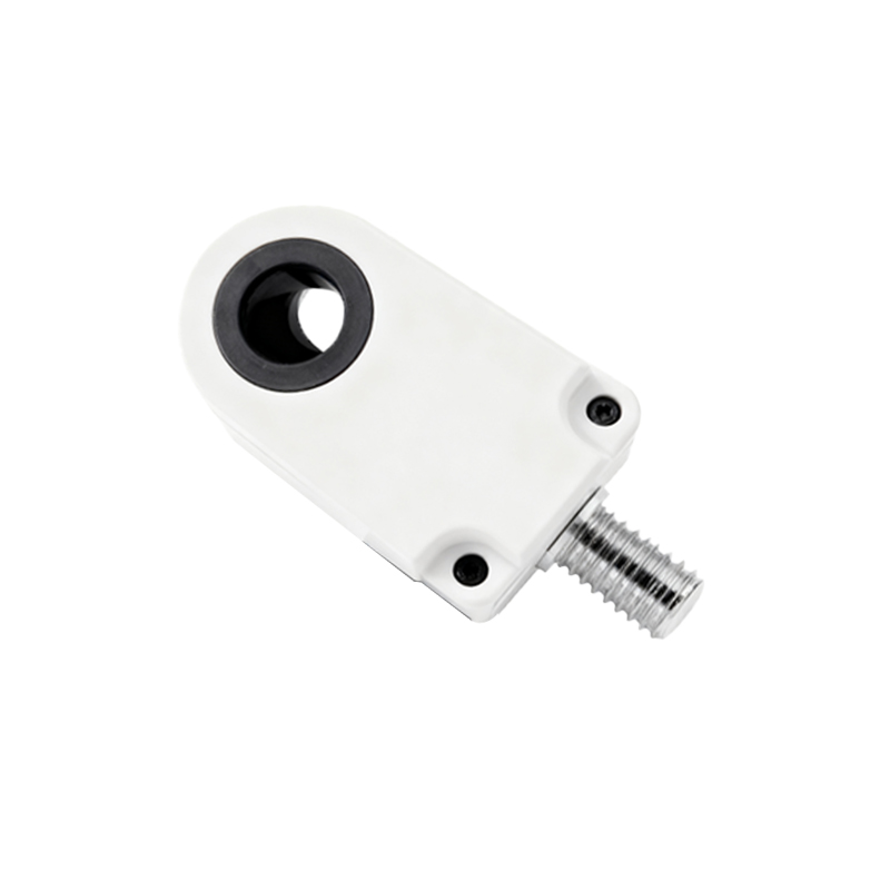
Capacitive proximity sensor images share similarities with inductive types but often feature a larger sensing face or a adjustable sensitivity potentiometer visible on the housing. The sensing surface might be made of a different composite material to facilitate the detection of non-metallic objects. Product galleries frequently show these sensors in context, such as detecting liquid levels through a glass or plastic tank wall, highlighting their material versatility. The imagery helps distinguish them from inductive models at a glance.
Photoelectric sensors, used for displacement and presence detection, present a distinct visual profile. Images clearly show the separate or integrated components: the transmitter (often with a red or infrared LED window) and the receiver. For diffuse-reflective types, a single unit with both elements is standard. Through-beam models are shown as a pair. High-quality photos will indicate the light spot size and beam pattern. Laser-based displacement sensor images emphasize precision, often showing a pinpoint laser dot on a target surface. Diagrams accompanying these images graphically depict the sensing methods—opposed, retro-reflective, diffuse—making the operational principle instantly comprehensible.
Ultrasonic sensor images often display a transducer face with a distinctive textured surface (acoustic membrane). They may appear bulkier than other types. Application-oriented images are critical here, showing the sensor mounted above a material roll or liquid surface, with graphical overlays indicating the conical sound beam's spread angle, a vital factor for avoiding false echoes from nearby objects.
Beyond the sensor itself, installation images are a treasure trove of practical information. Photos depicting correct and incorrect mounting—such as ensuring adequate flush-mounting clearance, avoiding sensor-to-sensor interference (especially for inductive types), and proper alignment for photoelectric and ultrasonic models—are extremely valuable. Wiring diagram images, showing connections to PLCs (Programmable Logic Controllers) like Siemens S7 or Allen-Bradley ControlLogix, and power supplies, translate schematic symbols into real-world implementation.
In conclusion, a systematic analysis of proximity displacement sensor images bridges the gap between abstract specifications and physical reality. By critically evaluating housing design, sensing face details, status indicators, connector types, and application context visuals, engineers and technicians can make more informed decisions, ensure optimal installation, and accelerate diagnostic processes. Always consult the manufacturer's detailed dimensional drawings and application notes alongside product imagery for a complete technical understanding.