In the realm of industrial automation and embedded systems, the integration of proximity sensors with microcontroller platforms like the Arduino Uno represents a fundamental and powerful combination. This guide, tailored for electrical engineers and automation professionals, details the practical steps and considerations for interfacing a common inductive proximity sensor with an Arduino Uno board, enabling reliable object detection in machinery and process control.
Proximity sensors are non-contact devices used to detect the presence or absence of an object within their sensing range. Inductive proximity sensors, specifically, are designed to detect metallic objects. They operate on the principle of electromagnetic induction. The sensor generates an oscillating electromagnetic field. When a metallic object enters this field, eddy currents are induced in the object, causing a change in the oscillation amplitude within the sensor's coil. This change is processed by the sensor's internal circuitry to trigger a switching output.
The Arduino Uno, based on the ATmega328P microcontroller, is an ideal prototyping platform for such integrations due to its straightforward I/O structure, robust community support, and compatibility with industrial signal levels when properly conditioned. Most standard industrial inductive proximity sensors operate on DC voltages (commonly 12-24V DC) and provide a digital output, typically in the form of an NPN (sinking) or PNP (sourcing) transistor configuration. For this example, we will consider a widely used 3-wire, NPN, normally-open (NO) sensor operating at 12V DC.
Required Components:
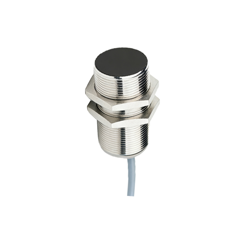
Arduino Uno board
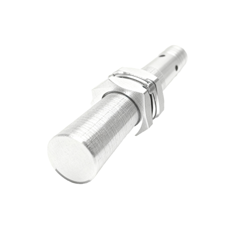
Inductive Proximity Sensor (12V DC, NPN, NO output)
12V DC Power Supply
Breadboard and jumper wires
10k Ohm resistor (for pull-up configuration)
Circuit Design and Interfacing:
A critical aspect of this interface is level shifting and signal conditioning. The Arduino Uno's digital pins are rated for 5V logic, while the sensor's switching element is part of a 12V circuit. Direct connection can damage the microcontroller.
1. Power Connections: Connect the 12V DC power supply's positive terminal to the sensor's brown wire (typically V+). Connect the power supply's negative terminal (GND) to both the sensor's blue wire (typically 0V) and the Arduino's GND pin. This establishes a common ground reference, which is essential.
2. Output Signal Conditioning (for NPN Sensor): The NPN output acts as a switch to ground. When no target is detected, the output transistor is off, and the signal wire (usually black) is effectively open. When a target is detected, the transistor turns on, connecting the signal wire to ground (0V). To translate this into a readable 5V logic signal for the Arduino, we use a pull-up resistor.
Connect the sensor's black signal wire to one leg of the 10k Ohm resistor.
Connect the other leg of this resistor to the Arduino's 5V pin. This is the "pull-up" to 5V.
Connect the junction between the sensor's signal wire and the 10k Ohm resistor to a digital input pin on the Arduino (e.g., Pin 2). This point will be at 5V (HIGH) when the sensor is idle (transistor OFF) and will be pulled down to near 0V (LOW) when the sensor activates (transistor ON, connecting to ground).
Arduino Firmware (Sketch):
The code is straightforward, involving pin mode declaration and digital reading.
``cpp
const int sensorPin = 2; // Digital pin connected to sensor signal
void setup() {
Serial.begin(9600); // Initialize serial communication for monitoring
pinMode(sensorPin, INPUT); // Configure the pin as an input
}
void loop() {
int sensorState = digitalRead(sensorPin); // Read the state of the pin
if (sensorState == LOW) {
Serial.println("Target DETECTED"); // Sensor active, transistor ON (LOW)
// Add control logic here: activate a relay, increment a counter, etc.
} else {
Serial.println("No target"); // Sensor idle, transistor OFF (HIGH)
}
delay(100); // Short delay for stability and readable serial output
}
``
Industrial Considerations:
Noise Immunity: In electrically noisy industrial environments, use shielded cables for the sensor and keep wiring away from high-voltage AC lines. The internal design of proximity sensors offers good noise immunity, but proper installation is key.
Sensor Selection: Choose a sensor with an appropriate sensing range, housing material (e.g., stainless steel for harsh environments), and output configuration (N