Proximity sensors are essential components in industrial automation, enabling non-contact detection of objects. Proper wiring is critical for reliable operation and safety. This tutorial provides a step-by-step guide with clear diagrams to help engineers and technicians correctly wire various types of proximity sensors.
First, understand the sensor type: inductive, capacitive, or magnetic. Inductive sensors detect metallic objects, capacitive sensors detect both metallic and non-metallic materials, and magnetic sensors respond to magnetic fields. Each type has specific wiring requirements.
For a typical 3-wire DC proximity sensor, the wiring process is as follows:
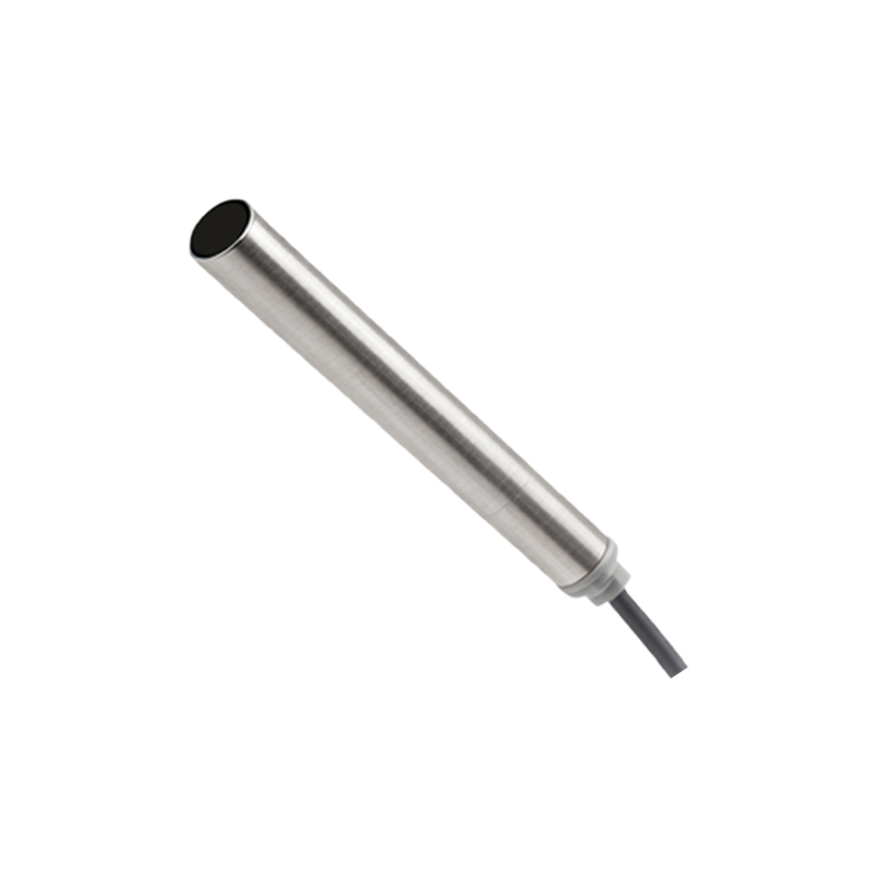
1. Identify the wires: brown (positive), blue (negative), and black (output).
2. Connect the brown wire to the positive terminal of the DC power supply (usually 10-30V DC).

3. Connect the blue wire to the negative terminal of the power supply.
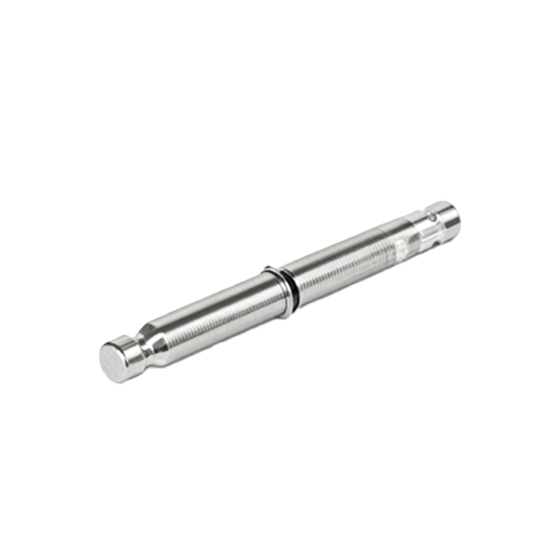
4. Connect the black wire to the load (e.g., PLC input, relay).
5. Ensure proper grounding and shield the cable if necessary to reduce electrical noise.
For 2-wire AC sensors, connect one wire to the AC power source and the other to the load. These sensors are simpler but require careful consideration of voltage drop.
Always refer to the manufacturer's datasheet for specific voltage ratings, current limits, and wiring diagrams. Incorrect wiring can lead to sensor damage, false triggers, or safety hazards. Use appropriate tools, such as wire strippers and screwdrivers, and follow lockout/tagout procedures during installation.
Testing is crucial after wiring. Apply power and bring a target object within the sensing range. Verify the output signal using a multimeter or PLC monitoring software. Adjust the sensor position if the detection is inconsistent.
Maintenance tips include regular inspection for loose connections, corrosion, or physical damage. Keep the sensor face clean to ensure accurate detection.
Diagrams included in this tutorial illustrate common wiring setups:
- Diagram 1: 3-wire DC sensor connected to a PLC.
- Diagram 2: 2-wire AC sensor controlling a relay.
- Diagram 3: NPN vs. PNP output configurations.
- Diagram 4: Shielded cable connection for noise reduction.
By following this guide, professionals can ensure efficient and safe proximity sensor installation, reducing downtime and improving system performance. Always prioritize safety standards and consult experts for complex applications.