Proximity sensors are indispensable components in modern industrial automation, robotics, and safety systems. These devices detect the presence or absence of objects without physical contact, relying on electromagnetic fields, infrared light, or ultrasonic waves. Proper power supply is critical to their performance, longevity, and reliability. This guide details the essential steps and considerations for powering proximity sensors, tailored for electrical engineers and industry professionals.
First, identify the sensor type and its electrical specifications. Proximity sensors generally fall into two categories: inductive (for metallic objects) and capacitive (for both metallic and non-metallic materials). Each type has specific power requirements, typically outlined in the datasheet. Common voltage ratings include 10-30 V DC (direct current) for DC sensors and 90-250 V AC (alternating current) for AC sensors. Always verify the input voltage range, current consumption (usually 200 mA or less), and connection method (2-wire, 3-wire, or 4-wire). Using an incorrect power source can lead to malfunction, damage, or safety hazards.
For DC-powered sensors, a stable DC power supply is necessary. Most industrial DC sensors operate on 12 V DC or 24 V DC. Ensure the power supply matches the sensor's voltage tolerance—for instance, a 24 V DC sensor might accept 10-30 V DC. Connect the positive terminal of the power supply to the sensor's positive wire (often brown or red) and the negative terminal to the negative wire (blue or black). In 3-wire configurations, the third wire (typically black or white) is the output signal wire, which switches based on object detection. Use shielded cables in environments with electromagnetic interference (EMI) to prevent false triggers.
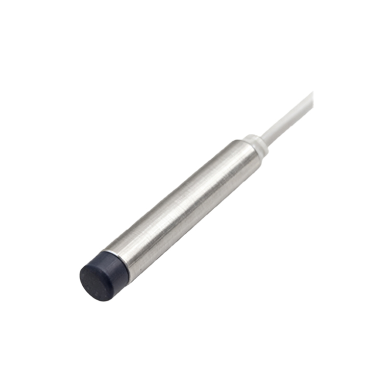
AC-powered sensors, common in high-voltage applications, require an AC power source like 120 V AC or 240 V AC. These sensors often have two wires: one for live (hot) and one for neutral. Connect the live wire to the power source's live terminal and the neutral wire accordingly. Note that AC sensors may generate more heat and have slower response times than DC sensors. Incorporate a fuse or circuit breaker in the power line for overload protection, adhering to local electrical codes.
Wiring practices are crucial for safety and efficiency. Always de-energize the circuit before connecting or disconnecting sensors. Use appropriate wire gauges based on current load and distance—for example, 18 AWG for short runs under 5 amps. For sensors in harsh environments (e.g., moisture, vibration), opt for IP67-rated connectors and conduits. Ground the sensor housing if specified, especially for capacitive types, to reduce noise and enhance stability.
Testing and troubleshooting ensure proper operation. After powering up, use a multimeter to check voltage at the sensor terminals. For DC sensors, measure between positive and negative wires; for AC, between live and neutral. The output signal can be verified with an oscilloscope or a PLC (Programmable Logic Controller). Common issues include no output (check power supply and wiring), intermittent detection (inspect for EMI or loose connections), and false positives (adjust sensitivity or reposition the sensor). Regular maintenance, such as cleaning the sensing face and checking for corrosion, prolongs sensor life.
In summary, powering proximity sensors involves selecting the correct voltage source, following precise wiring diagrams, and implementing protective measures. By adhering to manufacturer guidelines and industry standards, engineers can optimize sensor performance in diverse applications, from conveyor systems to machine safety interlocks.