Laser sensors represent a cornerstone technology in modern industrial automation, measurement, and control systems. Their ability to provide non-contact, high-precision, and high-speed detection makes them indispensable across a vast array of applications, from automotive assembly and electronics manufacturing to logistics and robotics. At its core, a laser sensor is an optoelectronic device that uses a focused beam of coherent light to detect, measure, or profile an object. The fundamental hardware architecture is elegantly designed yet sophisticated, comprising several critical components that work in concert to deliver reliable performance.
The journey begins with the Laser Diode, the heart of the sensor. Typically, visible red lasers (around 650 nm) or, for higher precision and eye-safety in demanding environments, Class 1 or Class 2 infrared lasers (e.g., 850 nm or 905 nm) are used. The diode generates the coherent light beam. Its performance is tightly controlled by a dedicated Driver Circuit. This circuit is not merely a power supply; it provides precise current regulation to ensure stable optical output, protects against voltage spikes, and often incorporates temperature compensation mechanisms. Fluctuations in diode temperature can shift the wavelength and output power, so thermal management via heat sinks or Peltier coolers is a critical hardware consideration for high-end sensors.
The emitted light then passes through Collimating Optics. These lenses transform the diverging beam from the diode into a parallel, tightly focused beam. The quality of these optics directly impacts the spot size and the minimum detectable object size. For distance measurement sensors, a perfectly collimated beam is essential. Following the collimation, the beam is directed towards the target.
The method by which the sensor processes the returning light defines its primary type. The two most prevalent hardware configurations are Through-Beam (Opposed) and Diffuse Reflective (Proximity) sensors.

A Through-Beam sensor consists of two separate hardware units: a transmitter and a receiver. The transmitter houses the laser diode and collimating optics. The receiver, positioned opposite, contains a photodetector (like a photodiode or phototransistor) and receiving optics. Detection occurs when the target object interrupts the beam path. This method offers the longest sensing ranges and highest immunity to target color, reflectivity, or surface angle. The receiver's hardware is optimized for sensitivity, often including filters to block ambient light.
A Diffuse Reflective sensor integrates both transmitter and receiver into a single housing. The emitted beam strikes the target and is scattered diffusely. A portion of this scattered light reflects back to the receiver optics within the same unit. A critical hardware component here is the optical axis separation. The transmitter and receiver lenses are mounted at a specific angle (convergent or parallel beam) to create a defined sensing field and a precise background suppression range. Advanced models use triangulation principles for precise distance measurement. The receiver side hardware is more complex, requiring precise alignment and often a Position Sensitive Device (PSD) or a CMOS/CCD array to determine the angle or position of the returning light spot.

The Photodetector is the crucial interface converting light information into an electrical signal. Silicon photodiodes are common for their speed and reliability. For precise triangulation-based distance sensors, a PSD or a CMOS linear array is used. The analog signal from the detector is typically weak and noisy.
This is where the Signal Processing Electronics take over. This hardware stage includes transimpedance amplifiers to convert the photocurrent to a voltage, followed by filters (band-pass filters tuned to the laser's modulation frequency) to eliminate DC ambient light interference and high-frequency electrical noise. Many modern laser sensors use a modulated laser beam. The driver circuit pulses the laser at a high frequency (e.g., tens of kHz), and the processing electronics are synchronized to detect only light modulated at that specific frequency. This technique, known as synchronous detection or lock-in amplification, dramatically improves signal-to-noise ratio and immunity to ambient light, a key hardware advancement.
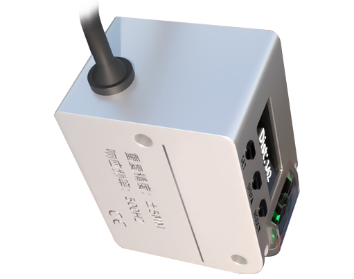
The processed signal is then fed into a Microcontroller or Digital Signal Processor (DSP). This is the brain of the sensor. It executes the detection algorithms, calculates distances based on time-of-flight or triangulation geometry, handles linearization of analog signals, and manages user interfaces (like teach-in buttons or LED indicators). It also communicates with the external world via Output Interfaces. These are hardware circuits providing switching outputs (NPN/PNP transistors for discrete signals), analog outputs (0-10V, 4-20mA for proportional measurement), or digital communication ports (IO-Link, RS-232, Ethernet/IP, PROFINET). IO-Link, in particular, is becoming a standard, allowing for parameterization, detailed diagnostics, and process value transmission through a single 3-wire cable.
Finally, the Housing and Connector form the critical protective shell. Rated typically at IP67 or IP69K for industrial environments, the housing protects delicate internal components from dust, water, oils, and mechanical shock. It also ensures stable mounting and precise alignment. The electrical connection is usually via a robust M8 or M12 circular connector, standard in factory automation.
In summary, the hardware of a laser sensor is a meticulously engineered fusion of optoelectronics, analog circuit design, digital processing, and rugged mechanical packaging. Each component, from the temperature-stabilized laser diode to the noise-filtering electronics and the industrial-grade housing, plays a vital role in determining the sensor's range, accuracy, speed, and reliability. Understanding this hardware interplay is essential for engineers to select the right sensor, integrate it effectively, and troubleshoot issues in the field, ensuring optimal performance in the most demanding automation tasks.