Laser displacement sensors are non-contact measurement devices that utilize laser triangulation to determine the distance to a target object with high precision. The core of their operation can be best understood through a detailed examination of the working principle diagram. This diagram visually breaks down the components and the light path, making the sophisticated technology accessible.
At the heart of the system is a laser diode, which emits a focused beam of coherent light. In the principle diagram, this is typically represented as a point source. This laser beam is projected onto the surface of the target object. The spot where the beam strikes becomes the measurement point. A critical factor here is the surface condition; diffuse reflective surfaces scatter light in many directions, while specular surfaces reflect it at a predictable angle. Most sensors are optimized for diffuse surfaces.
The key innovation is in the detection method. The light scattered or reflected from the target spot does not travel back along the exact same path. Instead, it is collected by a receiving lens positioned at a known angle relative to the laser emitter. This geometric arrangement forms a triangle—hence the term "laser triangulation." The emitter, the measurement point on the target, and the center of the receiving lens are the three vertices.
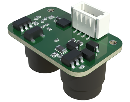
The receiving lens focuses the incoming scattered light onto a sensitive position-sensitive detector (PSD) or, more commonly in modern high-accuracy sensors, a Charge-Coupled Device (CCD) or Complementary Metal-Oxide-Semiconductor (CMOS) linear array. This is where the principle diagram becomes most illustrative. The diagram shows that as the target object's distance changes, the position of the focused light spot on the detector shifts linearly.
For instance, if the target moves closer to the sensor assembly, the angle of the reflected light changes, causing the focused spot to move to one end of the linear detector. If the target moves farther away, the spot moves to the opposite end. The sensor's internal processor continuously calculates the exact centroid of this light spot. Using the known baseline distance between the laser emitter and the receiving lens (the fixed side of the triangle) and the known angle, the processor applies trigonometric functions to compute the absolute distance to the target with remarkable speed and accuracy.
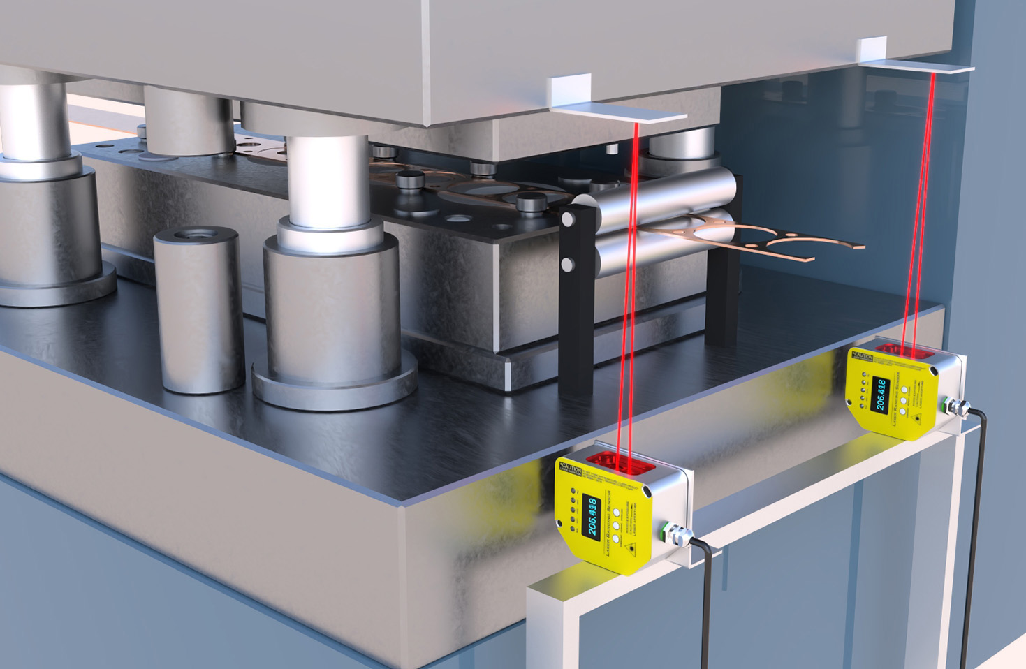
The principle diagram also often highlights additional optical elements. An aperture stop may be shown before the detector to control the amount of light and reduce noise from ambient light. Filters are sometimes included to allow only the specific wavelength of the laser light to pass, significantly enhancing signal-to-noise ratio in challenging environments.
Understanding this diagram clarifies several practical specifications. The measurement range is determined by the length of the detector and the focal length of the receiving lens. The stand-off distance is the optimal working distance from the sensor head to the target. The spot size, which affects resolution, depends on the laser's focus and the object's distance. A well-designed sensor minimizes optical aberrations that could distort the spot image on the detector.
Applications are vast because of this non-contact, high-speed principle. In automotive manufacturing, these sensors measure panel gaps and part dimensions. In electronics, they verify component coplanarity and solder paste height. In logistics, they sort packages by size. The fundamental principle remains the same, though specialized variants exist, such as confocal sensors for transparent materials or blue laser sensors for improved performance on organic surfaces.
In conclusion, the laser displacement sensor principle diagram is not just a schematic; it is a map of precision engineering. It translates the physical phenomenon of light reflection and geometric triangulation into a reliable, quantifiable electrical signal. By deconstructing the diagram—the laser emitter, the target, the receiving lens, and the position detector—one gains full appreciation for how these sensors achieve micron-level accuracy in real-time, enabling automation and quality control across modern industry. Their operation, elegantly captured in this diagram, is a testament to the effective application of fundamental physics to solve complex measurement challenges.