Proper installation is critical for the reliable and accurate operation of round proximity sensors in industrial automation systems. These non-contact devices, used for detecting the presence or absence of metallic objects, are ubiquitous in machinery, conveyor systems, and robotic cells. Incorrect mounting can lead to false triggers, reduced sensing range, premature failure, or even damage to the sensor itself. This guide provides a detailed, professional procedure for installing round inductive proximity sensors, the most common type, ensuring optimal performance and longevity.
Before beginning any installation, the first and most crucial step is to consult the sensor's datasheet and the machine's electrical diagrams. Verify the sensor type (e.g., NPN normally open, PNP normally closed), operating voltage (typically 10-30V DC), sensing distance, and housing material. Ensure you have the correct tools: appropriate wrenches, a mounting nut (usually supplied), a drill and tap set matching the sensor's thread size (common sizes are M8, M12, M18, M30), and necessary wiring tools.
The installation process begins with selecting and preparing the mounting location. The sensor must be positioned so that its sensing face can reliably detect the target object. Key considerations include the stated nominal sensing distance (Sn). For a standard sensor, the effective operating distance should be 0.8 x Sn to account for manufacturing tolerances and temperature variations. Ensure there is adequate clearance around the sensor body for the mounting nut and wiring conduit. The mounting surface should be rigid and free from excessive vibration.
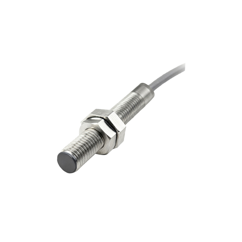
Next, prepare the mounting hole. If installing in a metal bracket or machine frame, drill a hole to the correct diameter for the sensor's threaded barrel. For a flush-mountable sensor, the hole can be the same diameter as the barrel. For non-flush mountable sensors (which offer longer ranges), you must ensure the hole is large enough so that the surrounding metal does not interfere with the electromagnetic field. After drilling, tap the hole with the correct thread pitch. Clean the hole thoroughly to remove all metal shavings, which could fall into the sensor or cause electrical shorts.
Now, mount the sensor. First, pass the sensor's cable or connector through the mounting hole from the front. If using a pre-wired sensor, handle the cable gland with care to avoid damaging the seal. Screw the sensor's threaded barrel into the tapped hole by hand until it is finger-tight. Then, use the supplied mounting nut or a wrench to secure it. Do not overtighten. Excessive torque can crack the sensor's housing, distort the threads, or damage the internal potting material. The sensor should be seated firmly without strain. For sensors with built-in mounting nuts, tighten the nut against the mounting surface, not by twisting the sensor body.
A critical and often overlooked step is aligning the sensor relative to the target. The sensing face must be parallel to the approach surface of the target object. Angular misalignment can drastically reduce the effective sensing distance. For optimal detection, the target should approach the sensor axially. Also, maintain proper clearance from other metal objects. The installation must respect the "non-sensing zone" typically indicated on the sensor's housing. Other nearby metal structures, especially ferrous ones, within this zone can influence the magnetic field and cause unstable operation. A general rule is to maintain a distance of at least one sensor diameter from adjacent metal surfaces.
Wiring comes next. Disconnect all power to the circuit before making any electrical connections. Most round proximity sensors have a 3-wire or 4-wire configuration. For a standard 3-wire DC sensor: connect the brown wire to the positive DC supply (+V), the blue wire to the negative DC supply (0V), and the black wire to the load (e.g., the input of a PLC, relay, or indicator). Double-check the wiring against the datasheet diagram, as colors can vary by manufacturer. Use crimped ferrules on stranded wires for a secure connection in the terminal block. Ensure the cable is routed away from high-voltage power lines and motor leads to prevent electrical noise interference. Secure the cable with clamps to prevent pull-out stress on the sensor's cable gland.
After mechanical mounting and electrical connection, perform functional testing. Re-apply power. Use the intended target material (e.g., mild steel) to test detection. Slowly bring the target toward the sensing face. Observe the sensor's output indicator LED (if equipped) and the response on the connected controller. Verify that the sensor activates consistently at the expected distance and that there is no "chatter" or intermittent operation. Test with the machine in its normal operating cycle if safe to do so, checking for any false triggers caused by vibration, other passing objects, or electrical noise.
Finally, implement protective measures. In harsh environments, consider adding