In the realm of industrial automation and electrical engineering, proximity sensors are indispensable components for non-contact detection, position sensing, and object counting. Ensuring their reliability and accuracy is paramount, which is where specialized proximity sensor testing instruments come into play. This guide delves into the core instruments, methodologies, and best practices for effective sensor validation and troubleshooting.
The cornerstone of any testing regimen is the signal simulator and analyzer. Modern digital oscilloscopes with high sampling rates are essential for visualizing the output waveforms of inductive, capacitive, and photoelectric proximity sensors. Engineers can precisely measure response time, pulse duration, and signal integrity under various conditions. For inductive sensors, which detect metallic objects, a variable-frequency signal generator paired with a calibrated metal target disc is crucial. This setup allows for the precise determination of the sensor's switching frequency, repeat accuracy, and the influence of different metals (e.g., steel, aluminum, brass) on its sensing distance.
Environmental simulation chambers represent another critical category of test equipment. Proximity sensors often operate in harsh conditions involving extreme temperatures, humidity, vibration, or electromagnetic interference (EMI). Climate chambers can subject sensors to thermal cycling from -40°C to +85°C or beyond, verifying thermal drift and long-term stability. Concurrently, EMI testers and vibration tables simulate real-world industrial noise and mechanical stress, ensuring the sensor's immunity and robust housing integrity.
For precise distance and hysteresis measurement, a laser displacement sensor or a high-accuracy linear positioning stage is employed. Hysteresis—the difference between the switch-on and switch-off points—is a key performance parameter. By mounting the sensor on a micrometric stage and moving a standard target toward and away from the sensing face, engineers can plot accurate characteristic curves. This data reveals not only the nominal sensing distance (Sn) but also the operational tolerance and any potential linearity errors.
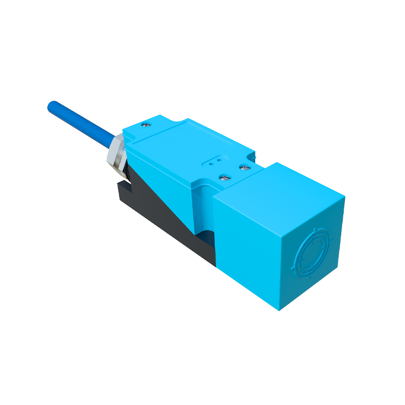
When dealing with analog output sensors (e.g., 4-20mA, 0-10V), a precision multimeter and a programmable load are mandatory. The test involves verifying the output current or voltage across the entire sensing range, checking for linearity, and ensuring proper behavior under load variations. For digital interfaces like IO-Link, which is becoming increasingly prevalent, a dedicated IO-Link master tester is necessary. This instrument can read and write sensor parameters, monitor process data, and diagnose communication faults, enabling advanced condition monitoring and predictive maintenance strategies.
A fundamental yet vital instrument is the gap-setting gauge. These are simple, calibrated non-ferrous and ferrous plates of specific thicknesses used for the quick verification of a sensor's installation gap, especially for cylindrical models in mounting brackets. Furthermore, a high-quality DC power supply with adjustable voltage (typically 10-30V DC for most models) is required to test the sensor's performance at the lower and upper limits of its supply voltage specification, checking for any dropouts or erratic behavior.
The testing procedure itself follows a logical sequence. Initial visual and mechanical inspection is followed by basic electrical tests for short circuits and leakage current. Subsequently, functional testing under nominal voltage with standard targets is performed. Then, parametric tests—switching frequency, response time, temperature drift—are conducted. Finally, stress tests involving voltage fluctuations, load changes, and environmental extremes validate robustness.
Best practices dictate maintaining a calibrated set of standard test targets, documenting all test results for traceability, and adhering to relevant international standards such as IEC 60947-5-2. Understanding the sensor's datasheet specifications is the first step; the right instruments provide the means to verify them. In conclusion, a well-equipped lab with these proximity sensor testing instruments empowers electrical engineers to ensure optimal system performance, reduce machine downtime, and implement sophisticated Industry 4.0 solutions with confidence. The investment in precise testing directly correlates with enhanced reliability and safety in automated systems.