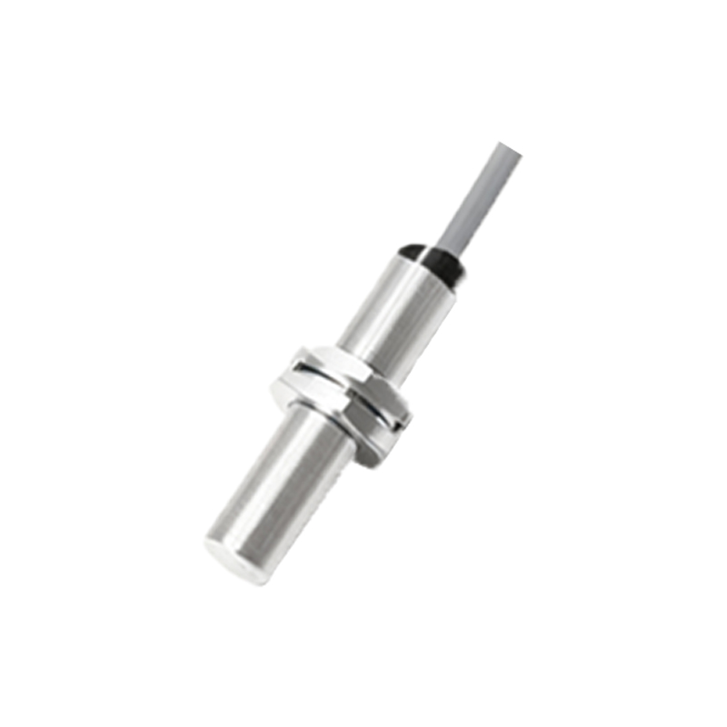
Proximity vibration sensors, often referred to as proximity probes or eddy-current sensors, are fundamental components in modern industrial predictive maintenance and condition monitoring systems. Their primary function is to non-contactively measure the vibration and relative position of a rotating shaft or other metallic target relative to the sensor tip. Understanding their operational principle is key to effective application in machinery health assessment.
The core technology behind most industrial proximity vibration sensors is the principle of eddy currents. The sensor system typically consists of a probe, an extension cable, and a driver oscillator/ demodulator module (often called a proximitor). The probe itself contains a coil of fine wire wound around a ferrite core. The oscillator within the driver module sends a high-frequency alternating current (typically 1-2 MHz) through this coil. This generates a high-frequency electromagnetic field that radiates from the probe tip.
When this electromagnetic field encounters a conductive target material (such as a steel shaft), it induces circular electrical currents on the surface of the target. These are the eddy currents. According to Lenz's Law, these eddy currents generate their own opposing magnetic field, which interacts with the field from the probe coil. This interaction effectively changes the impedance (a combination of resistance and inductance) of the probe coil. The key variable is the distance, or gap, between the probe tip and the target. As this gap decreases, more eddy currents are induced, causing a greater change in the coil's impedance. Conversely, as the gap increases, the effect weakens.
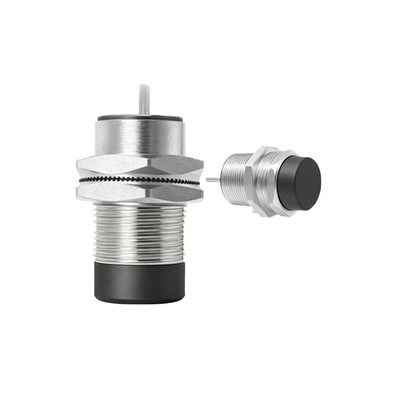
The driver module is precisely engineered to detect this change in impedance. It converts the impedance variation into a proportional, linearly changing DC voltage signal. This output voltage is directly and linearly related to the distance (gap) between the probe and the target. A typical calibration might be 200 mV/mil (7.87 V/mm). This DC voltage represents the average gap or the static position of the shaft within its bearing (e.g., for measuring shaft position or bearing clearance).
For vibration measurement, the dynamic component is extracted. When the shaft vibrates, the gap between the probe and the shaft surface changes dynamically at the vibration frequency. This causes a dynamic variation in the coil impedance, which the driver module demodulates. The resulting output signal contains both the static DC voltage (for position) and a superimposed AC voltage (for vibration). This AC component, representing the dynamic motion, can be analyzed for its amplitude (peak-to-peak displacement in mils or microns) and frequency, providing critical insights into machine condition such as unbalance, misalignment, or bearing defects.
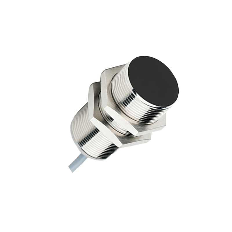
Several factors are crucial for accurate measurement. The target material must be electrically conductive; ferrous steels provide the strongest signal, while aluminum or other non-ferrous metals require specific calibration. The target must also be large enough and flat enough to ensure the eddy current field is fully contained. Temperature affects both the probe and the target material; high-temperature probes and stable driver electronics are used in demanding environments. Proper installation, including secure mounting and correct gap setting, is paramount.
The primary application of proximity vibration sensors is in monitoring radial vibration of shafts in rotating machinery like turbines, compressors, pumps, and motors. They are mounted perpendicular to the shaft, often in orthogonal pairs (X and Y directions) to determine the shaft centerline motion orbit. They are also extensively used for axial position measurement to monitor thrust bearing wear. In condition monitoring systems, the data from these sensors enables the detection of incipient faults, preventing catastrophic failures and enabling planned, cost-effective maintenance.
Compared to other vibration sensors like accelerometers or velocity sensors, proximity probes offer the unique advantage of directly measuring relative displacement of the shaft itself, independent of the bearing housing motion. This provides a clear picture of the rotor dynamics. Their non-contact nature eliminates wear and allows measurement on high-speed machinery where physical contact is impossible. In summary, the eddy-current principle provides a robust, reliable, and precise method for monitoring the vital signs of critical industrial machinery, forming the backbone of many predictive maintenance programs.