Proximity sensors are critical components in modern industrial automation, providing non-contact detection of objects for positioning, counting, and safety applications. Proper calibration is essential to ensure their reliability, accuracy, and longevity. Incorrectly calibrated sensors can lead to production errors, machine downtime, and safety hazards. This guide outlines a systematic approach to calibrating inductive, capacitive, and ultrasonic proximity sensors, adhering to industry best practices.
Before initiating calibration, gather the necessary tools: the sensor's datasheet, a set of certified calibration targets (made of the correct material, e.g., mild steel for inductive sensors), a precision distance gauge or feeler set, a stable power supply matching the sensor's specifications, and a multimeter or oscilloscope for signal verification. Always consult the manufacturer's documentation for model-specific parameters, as procedures can vary significantly.
The foundational step is environmental preparation. Ensure the sensor and target area are clean, free from debris, metal chips, or excessive moisture that could interfere with sensing. For capacitive sensors, especially, surrounding materials and environmental factors like humidity can drastically affect performance. Power down the equipment following lockout-tagout (LOTO) procedures to ensure safety. Mount the sensor securely in its operational fixture, as vibration or movement can alter the sensing gap.
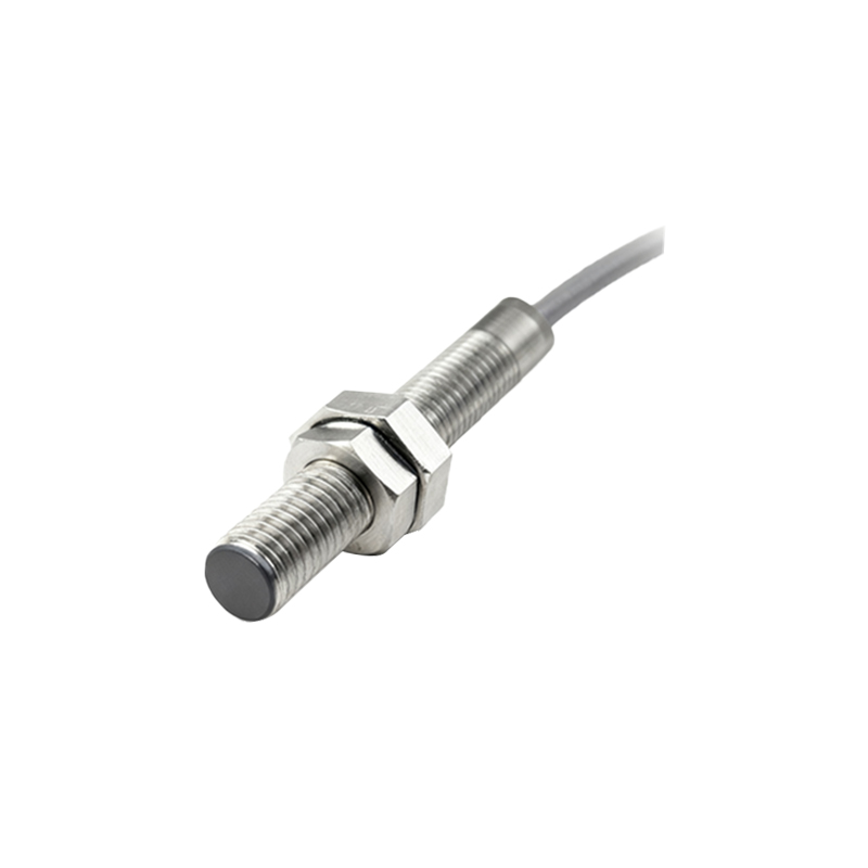
The core calibration process involves setting the sensing distance, often called the "operating point" or "switch point." For a standard inductive proximity sensor, follow these steps:
1. Establish Baseline: Connect the sensor to its specified voltage. Using the manufacturer's stated nominal sensing distance (Sn) as a reference, position the standard target at this distance. The sensor should typically be in its active state (output switched).
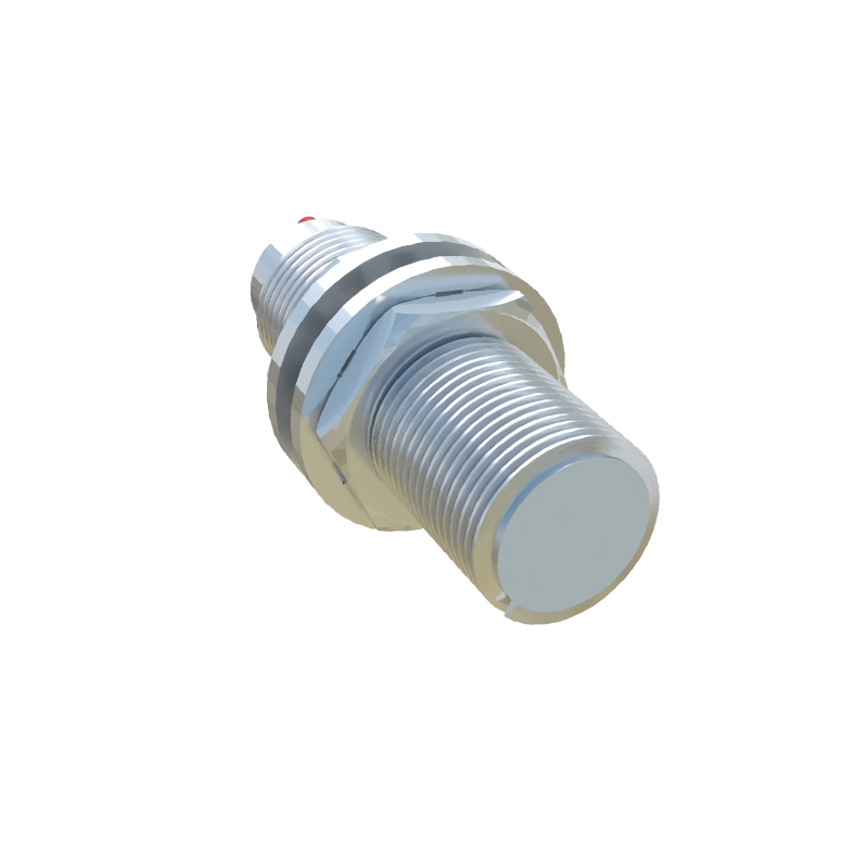
2. Determine Actual Sensing Distance: Slowly move the target toward the sensor face until the output state changes (e.g., from OFF to ON). Mark this distance. Then, slowly retract the target until the output state changes back. The hysteresis—the difference between the switch-on and switch-off points—is normal, but the operative sensing point is usually the switch-on distance.
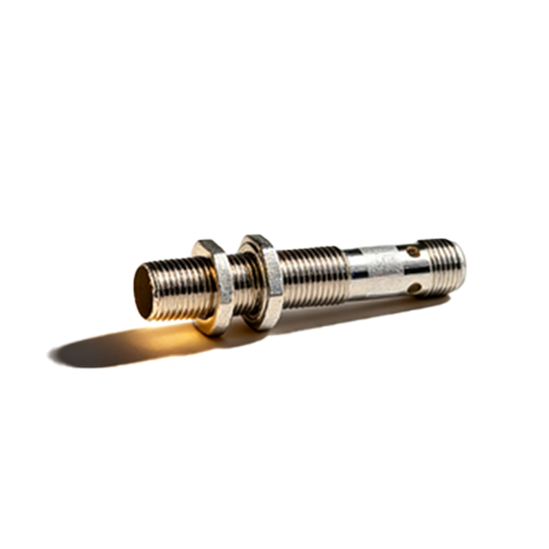
3. Adjust for Application: Rarely will the nominal distance be perfect for the application. The required sensing distance is often less than the nominal Sn to account for mechanical tolerances and temperature drift. A common rule is to set the actual operating gap at 50-80% of the nominal Sn. Use the precision gauge to set the target at this calculated distance.
4. Fine-Tune Sensitivity: Many sensors feature a potentiometer or teach-in function for sensitivity adjustment. With the target at the desired operational distance, adjust the potentiometer until the output just switches states. For teach-in models, follow the manual's procedure, which typically involves pressing a button when the target is in the correct position.
5. Verify and Document: Test the calibration by repeatedly introducing and removing the target. Verify the output signal with a multimeter or oscilloscope for consistency and the correct voltage/current level. Check for false triggers. Record the final set distance, sensitivity setting, and any environmental conditions.
For capacitive sensors, used for detecting non-metallic materials, the process is similar but emphasizes sensitivity to material composition and density. Calibration must be performed with the exact material to be detected. Adjust the sensitivity potentiometer so the sensor reliably detects the target material but does not trigger on background objects or changes in humidity.
Ultrasonic sensors require careful alignment of the sound cone. Calibration involves setting the switching thresholds for the near and far limits of the detection window. Use the manufacturer's software or built-in teach buttons to program these limits based on the target's position.
Post-calibration, implement a verification cycle. Simulate real-world conditions, including temperature variations if possible. Check for electrical noise interference by activating nearby motors or drives. Ensure the sensor's response time meets the application's cycle time requirements.
Common pitfalls to avoid include using incorrect target material, ignoring temperature coefficients (sensing distance can decrease at higher temperatures), failing to account for sensor flush or non-flush mounting styles, and neglecting to secure wiring, which can induce noise. Establish a preventive maintenance schedule to re-calibrate sensors periodically, as mechanical wear and environmental contamination can degrade performance over time.
A meticulously calibrated proximity sensor enhances system precision, reduces waste, and prevents unplanned stoppages. By methodically following these steps and leveraging manufacturer data, engineers and technicians can ensure these vital components perform optimally, contributing to efficient and safe industrial operations.