In industrial automation and machinery, proximity sensors are critical components for non-contact detection of objects. When a proximity sensor fails, it can lead to production downtime, safety hazards, and costly repairs. As a seasoned electrical engineer, I will guide you through a systematic approach to diagnosing and repairing a faulty proximity sensor. This guide assumes you have a basic understanding of electrical systems and follow all necessary lockout/tagout (LOTO) and safety protocols before beginning any work.
Step 1: Initial Diagnosis and Symptom Confirmation
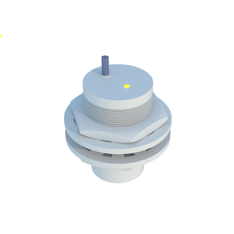
The first step is to confirm the sensor is indeed faulty. Common symptoms include: the machine not cycling, inconsistent object detection, a constantly lit or unlit indicator LED, or error codes on the PLC (Programmable Logic Controller). Begin by checking the machine's operation manual and recent fault history. Use a multimeter to verify that power is reaching the sensor. For a 3-wire DC sensor, check for the correct voltage (typically 10-30V DC) between the brown (positive) and blue (negative) wires. Ensure the load (often connected to the black wire) is not shorted. For AC sensors or 2-wire models, consult the datasheet for specific testing procedures.
Step 2: Visual and Physical Inspection
Power down and isolate the equipment completely. Inspect the sensor housing for cracks, dents, or signs of impact. Check the sensing face for accumulation of metal chips, dirt, oil, or coolant, which can severely attenuate the sensing field. Clean the face gently with a soft cloth and isopropyl alcohol. Examine the cable and connector for cuts, abrasions, or loose pins. A damaged cable is a frequent failure point, especially in high-vibration environments. Ensure the sensor is mounted securely and correctly aligned with the target; even a slight misalignment can cause failure.
Step 3: Electrical Testing and Parameter Verification
With power safely disconnected, perform continuity tests on the sensor's wiring. Reconnect power for live testing if safe to do so. Use your multimeter to monitor the output. For a normally open (NO) PNP sensor, the black wire voltage should switch from near 0V (off) to the supply voltage (on) when a target enters the sensing range. For an NPN sensor, the logic is inverted. An oscilloscope can provide a clearer picture of a switching signal if the failure is intermittent. Crucially, verify the target material, size, and sensing distance. Inductive sensors only detect metals, with different reduction factors for steel, aluminum, and copper. Capacitive sensors detect various materials but are sensitive to environmental changes. Ensure the target meets the specifications listed in the sensor's datasheet.
Step 4: Environmental and Interference Check
Proximity sensors can malfunction due to harsh environments. Check for excessive heat, which can degrade internal components. Look for signs of moisture ingress or corrosion. Electrical noise from nearby motors, variable frequency drives (VFDs), or welding equipment can cause erratic behavior. Ensure shielded cables are properly grounded at the control panel end only. Verify there are no other sensors or metal objects in close proximity that could cause mutual interference or a magnetic field for inductive models.
Step 5: Sensor Replacement and Calibration
If all previous steps point to a failed sensor, replacement is often the most efficient solution. Before removing the old sensor, note its exact model number, wiring configuration, and any adjustable settings (like potentiometers for sensitivity or time delay). Procure an identical or a compatible replacement from a reputable manufacturer. Install the new sensor, ensuring proper mounting torque and alignment. Reconnect the wiring precisely according to the color code or terminal diagram. After powering up, test the sensor's operation with the target. Some advanced sensors may require teach-in procedures or calibration via push-buttons or software. Document the replacement in the maintenance log.
Step 6: System Integration and Final Testing
Once the new sensor is installed and functioning in a standalone test, integrate it back into the machine's control sequence. Monitor the PLC input status to confirm reliable switching. Run the machine through several full cycles, testing the sensor under normal operating conditions. Observe for any recurrence of the initial fault.
Preventive Maintenance Tips
To avoid future failures, implement a preventive maintenance schedule. Regularly clean sensor faces, check mounting hardware, inspect cables for wear, and verify electrical connections. Keep a stock of critical spares for common sensor types in your facility.
Remember, not all sensor failures are repairable in the field. Many modern proximity