In the realm of home automation and DIY electronics, integrating a proximity sensor with a light bulb is a fundamental yet powerful project. It enables hands-free control, enhancing convenience, energy efficiency, and security. This guide provides a clear, step-by-step approach to successfully connecting a proximity sensor to control a light bulb, focusing on a common and safe method using a relay module.
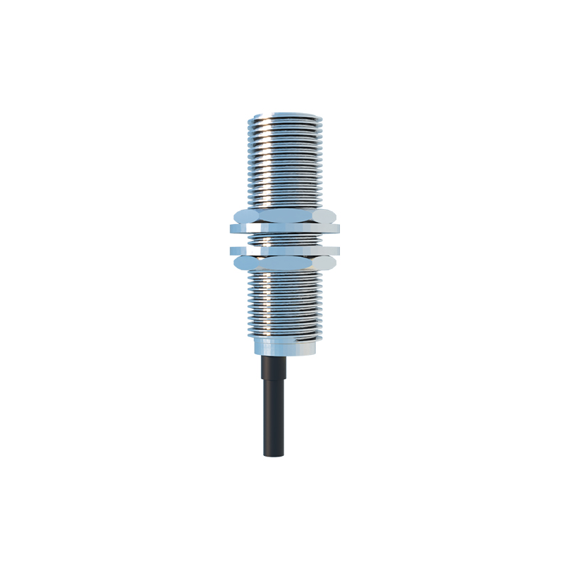
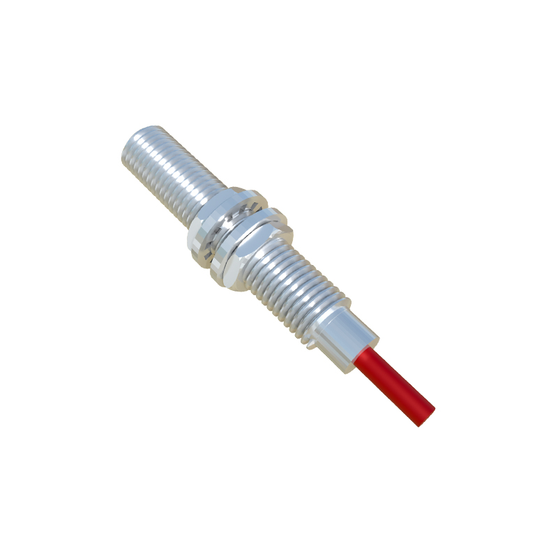
First, it's crucial to understand the core components. A proximity sensor is a device that detects the presence or absence of nearby objects without physical contact. Common types for DIY projects include infrared (IR) sensors and ultrasonic sensors. For this application, an IR sensor like the HC-SR501 Passive Infrared (PIR) sensor is widely used due to its affordability and reliability in detecting human motion. The second key component is the light bulb itself. For safety and simplicity, we will control a low-voltage DC bulb or, more commonly, use a relay to switch a standard household AC bulb. The relay acts as a critical intermediary; it is an electrically operated switch that allows the low-voltage, low-current signal from the sensor to safely control the high-voltage, high-current circuit required by the AC light bulb. You will also need a microcontroller, such as an Arduino board, to process the sensor's signal and command the relay. Necessary additional items include a power supply for the microcontroller and sensor (e.g., a 5V USB adapter or battery), a breadboard, jumper wires, and a lamp holder or socket.
The fundamental principle is straightforward. The proximity sensor continuously monitors its environment. When it detects an object (like a person) within its defined range, its output pin sends a signal (usually a change from LOW to HIGH voltage) to the microcontroller. The microcontroller is programmed to recognize this signal and, in response, trigger an output pin connected to the relay module. This action energizes the relay's coil, causing its internal mechanical switch to flip. This switch is connected in series with the AC power line going to the light bulb. When the relay switches, it completes the AC circuit, turning the bulb on. After the sensor no longer detects motion (following an adjustable delay period), the process reverses, and the bulb turns off.
Here is a detailed wiring guide. Always disconnect all power sources before making any connections. For the control circuit (low-voltage side): Connect the VCC and GND pins of the PIR sensor to the 5V and GND pins on the Arduino, respectively. Connect the sensor's OUT pin to a digital input pin on the Arduino (e.g., pin 2). Next, connect the relay module: its VCC and GND pins to the Arduino's 5V and GND. Connect the relay module's IN or SIG pin to a digital output pin on the Arduino (e.g., pin 7). For the load circuit (high-voltage side - Exercise Extreme Caution): Connect one wire from your AC power cord (e.g., the live wire) to one terminal of the relay module's switch (COM or Common terminal). Connect a wire from the other terminal of the relay switch (NO or Normally Open terminal) to one terminal of your lamp holder. Finally, connect the other terminal of the lamp holder back to the neutral wire of your AC power cord. This creates a safe switched circuit where the relay controls the flow of power to the bulb. Ensure all high-voltage connections are properly insulated and secured.
The Arduino requires a simple program (sketch). The code's logic involves initializing the sensor and relay pins, then in a continuous loop, reading the sensor's state. If the sensor is triggered (HIGH), the code sets the relay pin to HIGH, activating the relay and turning the bulb on. It typically includes a delay to keep the light on for a set period after motion ceases. A basic example would usedigitalRead() to check the sensor pin anddigitalWrite() to control the relay pin. This code can be easily modified to adjust sensitivity timers or add features like ambient light checking with a photoresistor to prevent activation during daytime.
Safety cannot be overstated. When working with AC mains voltage, if you are not completely confident, use a pre-made socket or seek assistance from a qualified person. Always enclose all AC wiring in a proper junction box. For absolute beginners, a safer alternative is to use a 12V DC bulb and a 12V power supply, eliminating the dangers of mains AC entirely. You can also explore pre-built smart bulbs and sensors that communicate via Wi-Fi or Zigbee, which require no direct electrical wiring for integration.
Potential applications are vast. This setup is perfect for creating automatic closet lights, pantry lights, under-cabinet lighting, security lights, or hallway night lights. By mastering this basic integration of a proximity sensor and a light bulb, you unlock the