Proper wiring is fundamental to the reliable operation of a laser distance sensor in any industrial application. Incorrect connections can lead to inaccurate measurements, sensor damage, or even system failure. This guide provides a comprehensive, step-by-step approach to wiring these sophisticated devices, adhering to standard industry practices and safety protocols.
Before initiating any wiring procedure, the first and most critical step is to consult the specific datasheet and installation manual provided by the sensor manufacturer. While general principles apply, pin configurations, voltage requirements, and communication protocols (e.g., analog 4-20mA, 0-10V, digital RS-485, IO-Link, Ethernet/IP) vary significantly between models and brands. Always disconnect power to the entire system before handling any electrical connections.
A typical laser distance sensor features a multi-pin connector or a set of screw terminals. The core connections usually include a power supply, ground, and output signals. For a standard DC sensor, identify the V+ (or +Vs) and V- (or 0V) terminals for the power supply, which is commonly 12-24V DC. The ground connection must be secure and, in many cases, should be connected to the system's common ground to minimize electrical noise.
The output wiring depends entirely on the selected interface. For an analog current output (4-20mA), you will typically connect the positive output wire to your PLC's or receiver's analog input module's positive terminal and the negative wire to the corresponding negative terminal. Ensure the loop power is supplied either by the sensor itself (active output) or by the receiving device (passive output), as specified in the manual. For a voltage output (0-10V), the wiring is similar, but attention must be paid to the load impedance to avoid signal degradation.
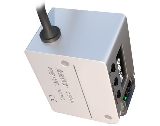
Digital interfaces require more careful wiring. For RS-485 communication, you will connect the A (or D+) and B (or D-) differential signal lines to the matching terminals on your host controller or converter. Implementing proper termination resistors (typically 120Ω) at both ends of the network is essential for signal integrity in long cable runs. Shielded, twisted-pair cables are mandatory for RS-485 and analog signals to protect against electromagnetic interference (EMI). The cable shield should be grounded at one end only, usually at the control panel, to prevent ground loops.
For sensors with discrete I/O, such as a teach-in trigger input or a limit switch output, connect these to the appropriate digital channels on your controller. Always verify the switching type (PNP sourcing or NPN sinking) to ensure compatibility with your PLC's input card. Mismatching PNP and NPN is a common wiring error.

After all physical connections are made and double-checked against the wiring diagram, apply power. Do not point the laser at reflective surfaces or people during initial testing. Use the manufacturer's software or configuration tool to verify communication and test the measurement output with known distances. Monitor the signal for stability, especially in electrically noisy environments.
Common pitfalls to avoid include using unshielded cables, exceeding the maximum cable length specified for the protocol, neglecting wire gauge for longer runs (which can cause voltage drop), and failing to secure strain relief on the sensor's cable gland. Proper wiring is not just about making a connection; it's about ensuring signal accuracy, system longevity, and operational safety. By following these methodical steps and prioritizing the manufacturer's documentation, engineers can ensure their laser distance sensing systems deliver precise and dependable performance.