Proper installation of proximity sensors is critical for ensuring reliable operation and maximizing performance in industrial automation systems. Among the most important considerations during installation is the mounting hole dimension, which directly impacts sensor alignment, sensing range, and environmental protection. This guide provides detailed insights into standard mounting hole sizes, tolerances, and best practices for various proximity sensor types, including inductive, capacitive, and photoelectric sensors.
Mounting holes for proximity sensors are typically designed to match industry-standard threaded or smooth-bore specifications. Inductive sensors, commonly used for metal detection, often feature M8, M12, M18, or M30 threaded housings, with corresponding hole dimensions. For example, an M12 sensor requires a mounting hole of approximately 12.2 mm to 12.5 mm in diameter, accounting for minor tolerances and ease of insertion. Non-threaded cylindrical sensors may need precise smooth holes with tighter tolerances, usually within ±0.1 mm, to prevent misalignment. Incorrect hole sizing can lead to mechanical stress, reduced sensing distance, or ingress of contaminants like dust and moisture, compromising the sensor's IP rating.
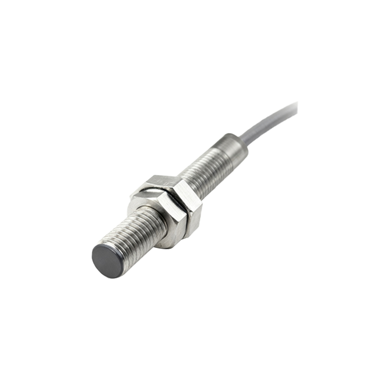
When designing mounting holes, engineers must consider the sensor's flange or nut dimensions. Many sensors incorporate a hexagonal nut or flange for secure fastening, requiring additional clearance around the hole. For instance, an M18 sensor with a standard nut might need a hole panel thickness of 1-3 mm and a surrounding flat surface to ensure proper seating. It is advisable to consult the manufacturer's datasheet for exact dimensions, as variations exist between brands and models. Additionally, factors like material thermal expansion, vibration, and electrical interference should influence hole placement and size. For high-vibration environments, using lock nuts or adhesive compounds can enhance stability without altering hole dimensions.
For capacitive and photoelectric sensors, mounting holes may differ due to housing shapes or lens requirements. Rectangular or square sensors often require tapped holes or mounting brackets, with hole patterns specified in technical drawings. Ensuring parallel alignment between the sensor face and target is crucial; even slight angular deviations can affect performance. In applications involving multiple sensors, consistent hole spacing and depth must be maintained to avoid cross-talk or signal interference. Using jigs or CNC machining for hole preparation can improve accuracy, especially in high-volume production setups.
In summary, adhering to precise mounting hole dimensions is essential for optimal proximity sensor functionality. Always verify specifications against application needs, and consider environmental factors during installation. Regular maintenance checks for hole integrity and sensor positioning can prevent downtime and extend sensor lifespan in demanding industrial settings.