In the realm of industrial automation and control systems, proximity sensors are indispensable components for non-contact object detection. Among the various types, 3-wire DC sensors are the most prevalent, and their operation is fundamentally defined by their output switching configuration: PNP and NNP. Grasping the distinction between these two types is critical for proper system design, wiring, and troubleshooting. This article delves into the technical principles, wiring schematics, and practical application considerations for PNP and NNP proximity sensors.
At their core, both PNP and NNP sensors are solid-state electronic switches. The terms PNP (Positive-Negative-Positive) and NNP (Negative-Negative-Positive) refer to the type of bipolar junction transistor (BJT) used in the sensor's output stage. This internal transistor dictates how the sensor interfaces with the load (e.g., a PLC input, relay, or indicator lamp) within the electrical circuit.
A PNP sensor is often described as a "sourcing" sensor. In its normal state (no target detected), the output terminal is electrically disconnected (open circuit). When a target enters the sensing range, the internal PNP transistor switches ON, connecting the output terminal to the positive supply voltage (+V). This action "sources" current from the sensor's output to the load. Therefore, the load must be connected between the sensor's output wire and the common negative (0V) or ground. The current flows from the sensor, through the load, and to ground. This configuration is commonly used in Europe and Asia.
Conversely, an NNP sensor is known as a "sinking" sensor. In its normal state, the output is again open. Upon detection, the internal NNP transistor switches ON, connecting the output terminal to the negative supply voltage (0V or ground). This "sinks" current from the load into the sensor. In this setup, the load must be connected between the positive supply (+V) and the sensor's output wire. The current flows from the positive supply, through the load, and into the sensor's output, which then connects to ground. This sinking configuration has been traditionally prevalent in North America and Japan.
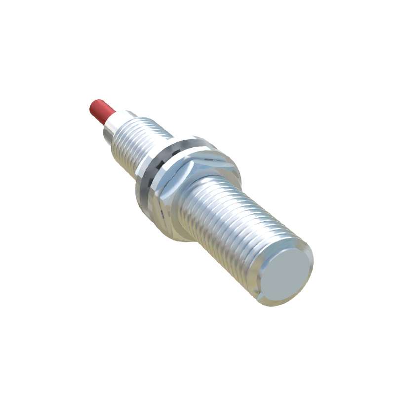
The wiring difference is paramount. Incorrectly matching a sensor type to a control system can lead to malfunction or permanent damage. Most modern Programmable Logic Controllers (PLCs) and DC input modules are designed to be compatible with either type, but their internal circuitry must be configured accordingly. A PLC input card wired for sinking (NNP) operation typically has its common terminal connected to +V, expecting current to flow into its input point. A card wired for sourcing (PNP) operation has its common connected to 0V, expecting current to flow out of its input point. Always consult the datasheets of both the sensor and the control device.
Beyond wiring, the choice between PNP and NNP can have implications for system safety and logic. In safety-critical applications, a "fail-safe" logic state is often desired. For instance, a PNP sensor that sources voltage when active might be chosen for a guard door interlock; a wire break or power loss would then be interpreted as a "door open" (safe) state because the voltage signal disappears. The logic interpretation (active-high vs. active-low) is directly tied to the sensor type and the PLC's input configuration.
When selecting a sensor, engineers must specify:
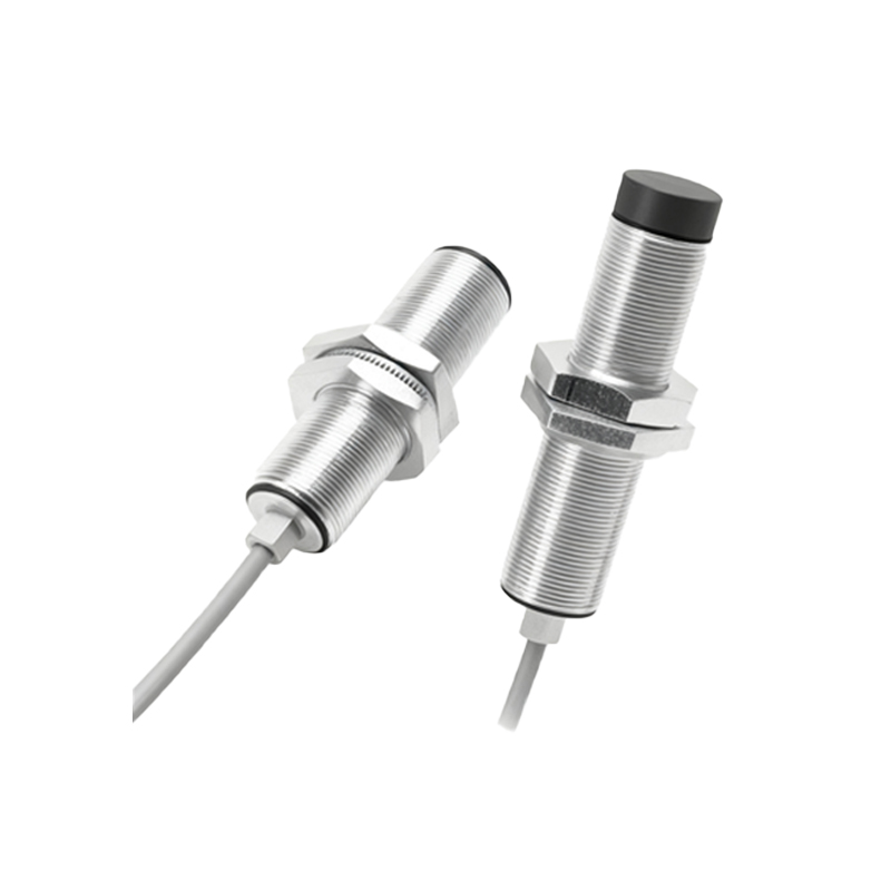
1. Sensing Technology: Inductive (for metals), capacitive, or ultrasonic.
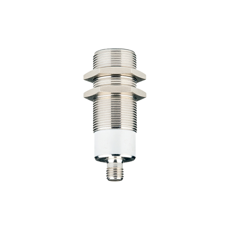
2. Output Configuration: PNP (sourcing) or NNP (sinking).
3. Output Function: Normally Open (NO) or Normally Closed (NC). A PNP-NO sensor outputs +V when activated. An NNP-NO sensor outputs 0V when activated.
4. Supply Voltage: Typically 10-30V DC.
5. Wiring Connection: Pre-wired cable or quick-disconnect connector.
In practice, many sensor bodies are marked with a wiring diagram. The standard color code for 3-wire DC sensors is: Brown for +V (positive), Blue for 0V (common/negative), and Black for the output signal. The functionality of the black wire—whether it sources or sinks current—defines it as PNP or NNP.
Understanding PNP and NNP is not merely academic; it is essential for efficient panel layout, reduced commissioning errors, and streamlined maintenance. As global standards continue to harmonize, many suppliers offer sensors in both configurations. However, the fundamental electrical principle remains: PNP sources current to the load, NNP sinks current from the load. By meticulously applying this knowledge, engineers ensure robust, reliable, and safe operation of automated systems, from simple conveyor lines to complex robotic cells