In the field of electrical engineering and industrial automation, proximity switch sensors are indispensable components for detecting the presence or absence of objects without physical contact. Their graphical symbols, standardized internationally, play a crucial role in circuit diagrams, schematics, and technical documentation. Understanding these symbols is essential for engineers, technicians, and designers to ensure accurate system integration and communication.
The graphical representation of proximity switch sensors follows conventions established by standards such as IEC 60617 and ANSI/IEEE 315. These symbols are designed to convey key operational characteristics visually, including the sensing method, output type, and electrical connections. Common types include inductive, capacitive, and magnetic proximity sensors, each with distinct symbol variations.
Inductive proximity sensors, used primarily for detecting metallic objects, are depicted with a coil-like icon adjacent to a switch representation. The symbol typically includes a diamond shape to indicate non-contact sensing, along with lines denoting the sensing face. Capacitive proximity sensors, capable of detecting both metallic and non-metallic materials, feature a similar structure but with added parallel plates to signify capacitance. Magnetic proximity sensors, often employed with permanent magnets or ferrous targets, incorporate a magnet symbol into the design.
Output configurations are also embedded in these graphical symbols. For instance, a normally open (NO) or normally closed (NC) contact is shown using standard switch symbology, combined with the proximity element. Additionally, symbols may include annotations for output types like NPN or PNP transistors in solid-state sensors, or relay outputs. Power supply connections, usually marked with + and - terminals, are integrated to clarify wiring requirements.
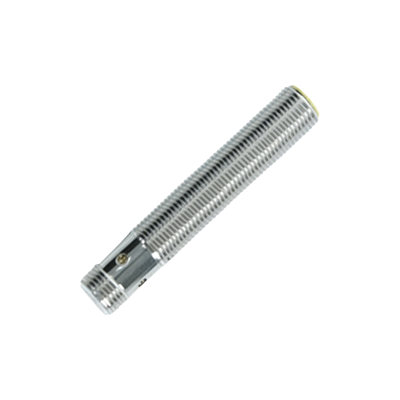
In circuit diagrams, proximity switch symbols are placed in context with other components, such as PLCs, relays, and actuators. Proper interpretation ensures correct ladder logic programming and system functionality. Misreading a symbol can lead to wiring errors, operational failures, or safety hazards. Therefore, familiarity with regional standards is vital, as symbols may vary slightly between IEC (common in Europe and Asia) and ANSI (prevalent in North America) systems.
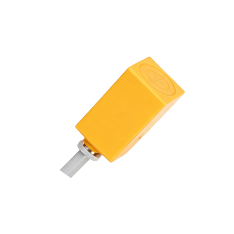
Advanced proximity sensors with integrated diagnostics or analog outputs feature additional graphical elements, like signal waves or diagnostic flags. These enhancements aid in troubleshooting and system optimization. As technology evolves, symbols are periodically updated to reflect new features, such as IO-Link connectivity or RFID capabilities, though core elements remain consistent for backward compatibility.
In practice, engineers must reference manufacturer datasheets alongside standard symbols, as some proprietary designs include unique markings. Training resources, including online courses and technical manuals, help professionals stay current with symbol usage. Ultimately, mastering these graphical symbols enhances design efficiency, reduces errors, and promotes global collaboration in electrical projects.

To summarize, proximity switch sensor graphical symbols are a universal language in electrical engineering. They encapsulate complex functionalities into simple, recognizable icons, bridging communication gaps across disciplines and borders. By adhering to international standards and continuous learning, professionals can leverage these symbols to build robust, automated systems that drive modern industry forward.