In industrial automation and control systems, proximity sensors are indispensable components, providing non-contact detection of metallic and sometimes non-metallic objects. Their reliability is paramount for ensuring smooth production flow, machine safety, and process accuracy. However, a persistent challenge faced by engineers and maintenance personnel is false triggering—an event where a sensor activates without the intended target being within its nominal sensing range. This phenomenon can lead to costly downtime, production errors, and even safety hazards. Understanding the root causes and implementing effective solutions is critical for maintaining system integrity.
The primary causes of false triggering can be categorized into environmental, electrical, mechanical, and sensor-specific factors.
Environmental Interference is a major contributor. The presence of other metallic objects in the vicinity, such as machine frames, moving parts, or even tools, can inadvertently be detected. Strong electromagnetic fields generated by nearby motors, variable frequency drives (VFDs), welding equipment, or high-current cables can induce voltages in the sensor or its cabling, mimicking a valid signal. For inductive sensors, different metals have varying effects on the sensing distance; a sensor calibrated for mild steel may behave unpredictably with aluminum or stainless steel, sometimes triggering erratically. Accumulation of metallic dust, chips, or conductive fluids on the sensor face can also create a false detection path.
Electrical Noise and Grounding Issues are perhaps the most common culprits. Electrical noise, or electromagnetic interference (EMI), can be conducted through power lines or radiated through the air. Poor shielding of sensor cables, especially when run in parallel with high-power lines, makes them susceptible to noise pickup. Inadequate or improper system grounding creates ground loops, leading to fluctuating reference potentials that the sensor's amplifier interprets as a target signal. Voltage spikes from inductive load switching (e.g., solenoids, contactors) on the same power supply can also cause transient false triggers.
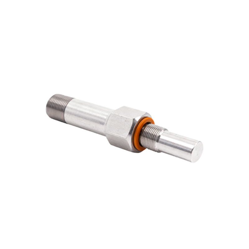
Mechanical and Installation Factors play a significant role. Excessive sensor vibration or shock can cause internal components to shift momentarily, triggering an output. Incorrect mounting, such as insufficient flush-mounting distance for shielded sensors or improper alignment, can cause the sensor to detect the mounting bracket or background material. Thermal expansion and contraction of machinery can subtly alter the gap between the sensor and its normal background, pushing it into the operating margin.
Sensor-Specific and Application Issues include selecting the wrong sensor type for the application. Using a standard inductive sensor to detect a small, fast-moving target might result in inconsistent sensing. Sensor deterioration over time, such as drift in oscillator characteristics or damage to the sensing face, reduces reliability. Furthermore, the physical and electrical characteristics of the target itself—its size, shape, material, and approach speed—must align with the sensor's specifications. An undersized target or one moving too quickly may cause erratic behavior.
Solutions and Best Practices require a systematic approach. Begin with Proper Sensor Selection and Installation. Choose a sensor with an appropriate sensing distance, switching frequency, and housing material for the environment. Ensure it is rated for the specific metal type if using inductive sensors. Follow mounting guidelines meticulously, maintaining recommended distances from other metals and backgrounds. Use shielded sensors in congested metallic environments.
Implement Robust Electrical Practices. Use shielded, twisted-pair cables for all sensor connections and ground the shield at the controller end only to avoid ground loops. Physically separate sensor cables from power cables by at least several inches, using separate conduits if possible. Employ filtered power supplies or line conditioners to suppress conducted noise. For DC sensors, consider using surge suppressors on inductive loads. Ensure a single-point, solid earth ground for the entire control system.
Environmental Management is key. Install protective guards or non-metallic shrouds to prevent buildup of debris on the sensor face. For areas with heavy EMI, consider sensors with enhanced noise immunity ratings or switch to analog-output sensors with programmable thresholds for better discrimination. In applications with multiple sensors in close proximity, select models with different operating frequencies or enable synchronization functions to prevent crosstalk.
Regular Maintenance and Monitoring cannot be overlooked. Establish a schedule for inspecting sensors for physical damage, cleanliness, and secure connections. Monitor system logs for intermittent faults that might indicate early signs of sensor drift or interference. For critical applications, consider implementing sensor diagnostics or using redundant sensing schemes for validation.
In conclusion, proximity sensor false triggering is a multifaceted problem with solutions rooted in careful planning, correct installation, and diligent maintenance. By systematically addressing potential sources of interference—environmental, electrical, and mechanical—engineers can significantly enhance the reliability of their sensing systems. A proactive approach to sensor selection and system design is far more cost-effective than troubleshooting sporadic failures on a production line. Investing time in understanding the operational environment and the sensor's limitations is the most reliable strategy to ensure consistent, trouble-free performance.