In industrial automation and machinery safety, proximity sensors are indispensable components. They detect the presence or absence of an object without physical contact, using electromagnetic fields, infrared light, or ultrasonic sound. Correct wiring is paramount for reliable operation and system safety. This guide details the standard procedures for wiring common types of proximity sensors, focusing on 3-wire DC and 2-wire AC models prevalent in control panels and machinery.
First, understand the sensor specifications. Always consult the manufacturer's datasheet for voltage ratings, current capacity, output type (NPN sinking or PNP sourcing for DC; NO/NC for AC), and housing material. Ensure the power supply matches the sensor's requirements. Common DC voltages are 10-30V DC, while AC sensors often use 90-250V AC. Mismatched voltage can cause permanent damage.
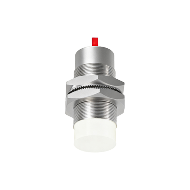
For a standard 3-wire DC inductive proximity sensor, identify the wire colors: typically brown (positive/+V), blue (negative/0V or common), and black (output signal). Some models may use different colors like white or gray, so verify with the manual. The wiring process is as follows:
1. Power Connection: Connect the brown wire to the positive terminal of your DC power supply (e.g., +24V). Connect the blue wire to the negative terminal (0V or ground). This provides operating power to the sensor's internal circuitry.
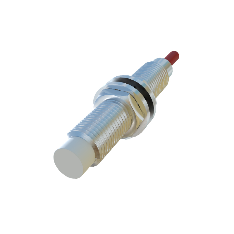
2. Output Connection: The black wire is the switched output. For an NPN sensor (sinking output), this wire will connect to the load (e.g., a PLC input, relay coil, or indicator lamp), and the other side of the load connects to the positive supply. When the sensor detects an object, the NPN transistor switches, connecting the black wire to 0V, completing the circuit to ground and activating the load. For a PNP sensor (sourcing output), the black wire supplies positive voltage to the load when active; the other side of the load connects to ground.
3. Shielding: If the cable has a shield or drain wire (often bare or green/yellow), connect it to earth ground at the control panel to minimize electrical noise interference, crucial in environments with variable frequency drives or heavy motors.
For 2-wire AC proximity sensors, wiring is simpler but requires careful consideration of load compatibility. These sensors have two wires, typically brown and blue. They act as a switch in series with the AC power line and the load.
1. Series Connection: Connect one wire (e.g., brown) to the AC line voltage (e.g., 120V AC). Connect the other wire (blue) to one terminal of the load. The remaining terminal of the load connects to the neutral line of the AC supply.
2. Leakage Current Consideration: AC sensors have a small leakage current even when off. The connected load must have a minimum current draw (usually specified, e.g., 5mA) to ensure proper switching. If the load resistance is too high (like a high-impedance PLC input), the leakage current may keep it falsely activated. Use a load resistor in parallel if necessary.
3. Protection: Incorporate a fuse (1-2A) in the line for short-circuit protection.
General best practices apply to all installations:
- Disconnect Power: Always lock out and tag out (LOTO) the main power before starting any wiring work.
- Secure Connections: Use appropriate wire gauges (often 18-22 AWG for signal lines) and crimp terminals for secure connections in terminal blocks. Avoid loose strands causing shorts.
- Routing: Keep sensor cables away from high-voltage power lines (maintain at least 20cm separation) to prevent inductive coupling and false triggers. Use conduit or cable trays for mechanical protection.
- Testing: After wiring, power the system and test with a target at the specified sensing distance. Use a multimeter to verify output voltage switching. For DC sensors, check that the voltage on the output wire toggles between near 0V (active for NPN) and supply voltage.
- Environment: Ensure the sensor is rated for the environment (e.g., IP67 for washdown areas). Avoid mounting metallic sensors flush with metal surfaces unless specifically designed for it, as this can reduce sensing range.
Troubleshooting common issues often relates to wiring. If a sensor fails to detect, check power and ground connections first. For erratic behavior, inspect for noise interference or voltage spikes; adding a snubber circuit or ferrite core may help. Remember, a correctly wired proximity sensor enhances machine efficiency, prevents downtime, and safeguards personnel by ensuring reliable object detection in automated processes. Always