Proximity sensors are fundamental components in modern industrial automation, robotics, and safety systems. Their primary function is to detect the presence or absence of an object within a specified range without physical contact. For electrical engineers and technicians, accurately measuring the output signal of these sensors is crucial for system integration, troubleshooting, and performance validation. This guide details the methodologies for measuring signals from the three main types of proximity sensors: inductive, capacitive, and photoelectric.
Understanding Proximity Sensor Output Types
Before measurement, identifying the sensor's output configuration is paramount. The two primary categories are Digital (Switching) and Analog outputs.
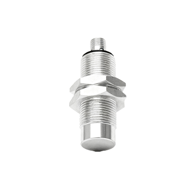
1. Digital (Switching) Outputs: These provide a simple ON/OFF signal. Common types include:
NPN (Sinking): The output switches the negative (0V) line to the load. Common in Asian and European designs.
PNP (Sourcing): The output switches the positive voltage line (e.g., +24V) to the load. Prevalent in North America.
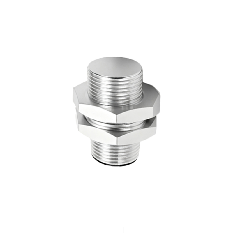
Push-Pull (Complementary): Combines NPN and PNP transistors, allowing connection to both sinking and sourcing inputs.
NAMUR: A two-wire, intrinsically safe analog output designed for hazardous areas, requiring a separate amplifier/barrier to convert to a standard switching signal.
2. Analog Outputs: These provide a continuous signal proportional to the distance to the target. Common standards are:
Voltage Output: Typically 0-10V or 0-5V.
Current Output: Most commonly 4-20mA (loop-powered), offering high noise immunity.
Measurement Tools and Setup
Essential equipment includes:
Digital Multimeter (DMM): For measuring DC voltage and current. Ensure it has appropriate accuracy and can measure mA for analog current loops.
Oscilloscope: Critical for analyzing signal integrity, rise/fall times, switching frequency, and diagnosing noise or bounce in digital signals.
Load Resistor: A resistor simulating the input impedance of the PLC or controller. For testing a PNP/NPN sensor, a resistor (e.g., 2kΩ) and an LED can create a simple test circuit. For 4-20mA loops, a precision 250Ω resistor is standard to convert the current to a 1-5V signal for measurement.
Stable Power Supply: Provides the specified sensor voltage (commonly 10-30V DC). Ensure it is correctly rated for the current draw.
Step-by-Step Measurement Procedures
For Digital (Switching) Output Sensors (e.g., Inductive PNP):
1. Wiring: Connect the power supply. For a 3-wire PNP sensor: Connect Brown wire (+V), Blue wire (0V/GND), and the Black wire (output) to your test load (e.g., a multimeter in voltage mode or a load resistor in series with the meter).
2. Power On: Apply the correct voltage. The sensor's power LED should illuminate.
3. Measure Voltage State:
OFF State: Without a target in the sensing range, measure the voltage between the output (Black) and 0V (Blue). It should be near 0V (leakage current may cause a small voltage).
ON State: Introduce a valid target (e.g., a metal object for inductive sensors) within the specified sensing distance. The output voltage should rise to near the supply voltage (e.g., ~24V). The multimeter reading confirms the switching action.
4. Oscilloscope Analysis: Connect the oscilloscope probe to the output terminal. Trigger a target approach and retreat. Observe the waveform for a clean, rapid transition. Measure the response time (rise/fall time) and check for signal bounce or noise.
For Analog Output Sensors (e.g., 4-20mA Capacitive):
1. Wiring (2-wire 4-20mA loop): Connect the positive terminal of the power supply to the positive sensor terminal. Connect the negative sensor terminal to one end of your precision 250Ω resistor. Connect the other end of the resistor to the negative terminal of the power supply, completing the loop.
2. Measurement Point: Place your multimeter (set to mA measurement mode) in series within this loop, OR measure the voltage drop across the 250Ω resistor.
3. Calibration and Sweep:
With no target (or at minimum distance), the measured current should be