In the realm of industrial automation and control systems, proximity switch sensors are indispensable components, providing non-contact detection of metallic and sometimes non-metallic objects. Their reliability is paramount for ensuring seamless operations in manufacturing, packaging, and assembly lines. However, a persistent and often perplexing issue encountered by maintenance engineers and system integrators is that of insufficient contact. This problem, while seemingly minor, can lead to catastrophic system failures, unplanned downtime, and significant production losses. This article delves into the root causes, diagnostic methods, and effective solutions for insufficient contact in proximity sensors, offering a comprehensive guide for industry professionals.
Insufficient contact, in this context, refers to a condition where the electrical output signal from the proximity sensor is weak, intermittent, or fails to meet the required threshold for the connected control system (e.g., a PLC input module). The sensor may detect the target, but the resulting signal is inadequate to reliably switch the connected load or register a definitive state change. This manifests as erratic machine behavior, missed counts, or false triggers.
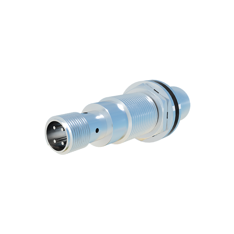
The primary culprits behind this issue are multifaceted. First and foremost is power supply instability. A proximity sensor requires a stable, clean DC voltage within its specified range (commonly 10-30V DC). Voltage drops, ripple, or electrical noise on the supply lines can directly weaken the output signal. Long cable runs without proper gauge sizing exacerbate voltage drop. Electrical noise from adjacent high-power equipment like variable frequency drives (VFDs), motors, or welding machines can induce interference on both the power and signal lines, corrupting the output.
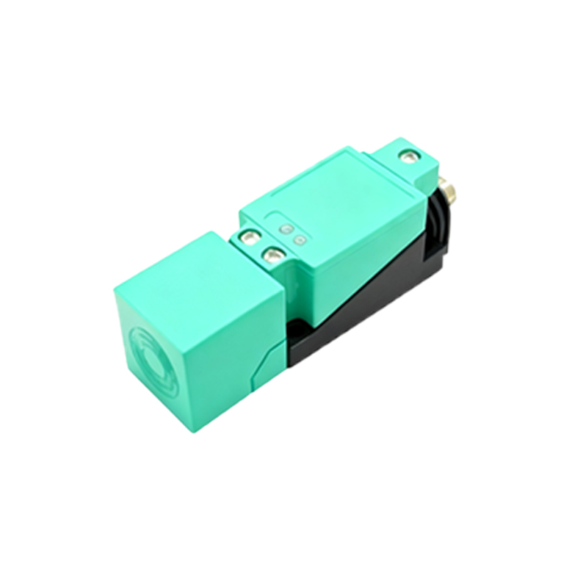
Secondly, sensor degradation and environmental factors play a critical role. Over time, the internal oscillator and amplifier circuitry of an inductive proximity sensor can drift from their optimal calibration due to component aging or thermal stress. Physical damage to the sensing face or housing can alter its electromagnetic field. Harsh environments pose significant threats: accumulation of metallic dust or swarf on the sensing face can dampen the effective sensing distance and signal strength; extreme temperatures can affect electronic component performance; and chemical exposure can corrode connections.
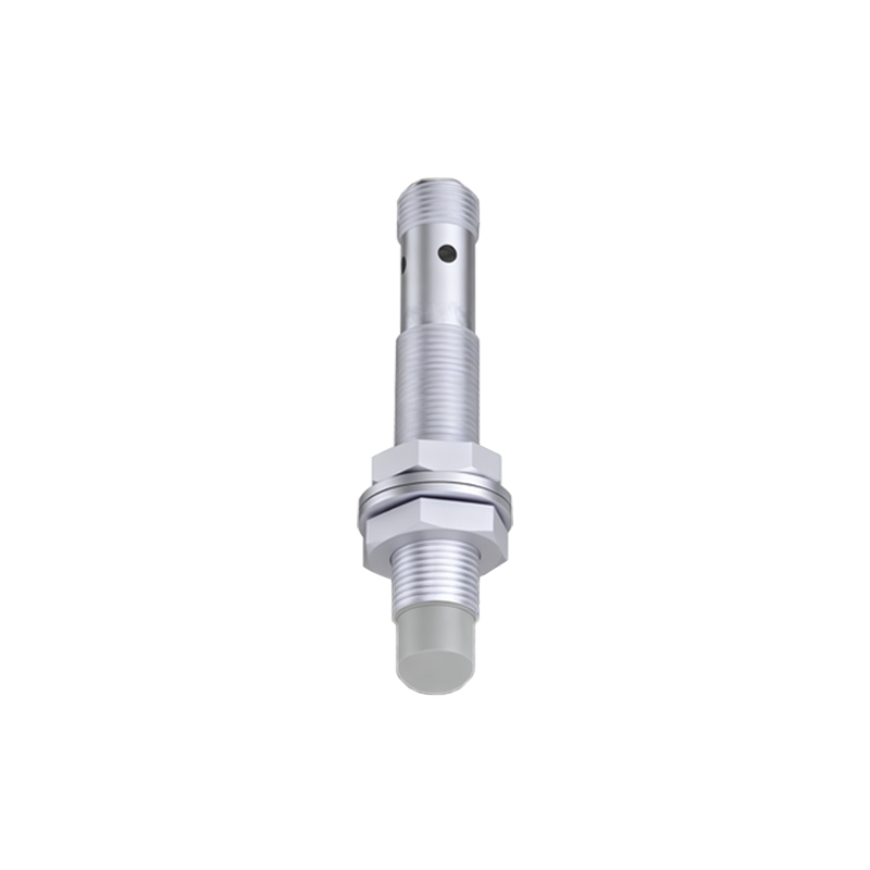
Thirdly, installation and setup errors are frequent contributors. An incorrect sensing distance is a classic mistake. Operating the sensor too close to its maximum rated distance leaves little margin for error, making the signal inherently weaker. Misalignment with the target object, or using an inappropriate target material/size (e.g., a non-ferrous metal for a standard inductive sensor, or a target smaller than the sensor face), results in a diminished response. Furthermore, improper grounding or the lack of a dedicated ground connection for the sensor and its load circuit creates a path for electrical noise and can lead to unstable signals.
Finally, load compatibility issues must be considered. Every proximity sensor has a specified maximum load current. Connecting a load that draws current near or beyond this limit can cause the output transistor to saturate poorly, resulting in a voltage drop across the output (insufficient "on" voltage). This is particularly noticeable when driving certain types of relays or long cables with high capacitance.
Diagnosing insufficient contact requires a systematic approach. Begin with a visual inspection for physical damage, contamination, and correct installation alignment. Next, use a digital multimeter to measure the power supply voltage at the sensor terminals under load to check for stability and adequacy. Monitor the output signal voltage directly at the sensor's output wire when a target is presented. A healthy PNP (sourcing) sensor should switch close to the supply voltage (e.g., 24V), and an NPN (sinking) sensor should switch close to 0V. Any significant deviation (e.g., a PNP sensor only reaching 18V) indicates a problem. An oscilloscope is the ultimate tool for revealing noise, ripple, or signal shape abnormalities that a multimeter might average out.
Resolution strategies are targeted at the identified cause. For power issues, ensure a dedicated, regulated power supply for sensors. Implement noise suppression measures: use shielded cables with the shield properly grounded at one end (typically the control panel end), install ferrite cores on cables near noise sources, and physically separate sensor wiring from power lines. For environmental protection, select sensors with appropriate IP (Ingress Protection) and IK (Impact Protection) ratings. Regularly clean the sensing face in dirty environments. Consider using sensors with extended temperature ranges or chemical-resistant housings if needed.
Re-evaluate the installation: adjust the sensor position to operate within 50-80% of its rated sensing distance for a robust signal. Ensure the target is correctly sized, aligned, and made of the appropriate material. For load issues, verify that the total load (including wire resistance) is within the sensor's specification. If driving a high-current relay directly, consider interposing a small intermediate relay or an opto-isolator module. In cases of aged or internally degraded sensors, replacement is often the