In the realm of industrial automation and machine control, proximity sensors are indispensable components. Their non-contact detection capability ensures reliability, longevity, and safety in countless applications, from assembly lines to robotic arms. A critical, yet often overlooked, specification for these devices is their operational life, typically defined by the maximum number of switching cycles. This article delves into the factors that limit the cycle life of proximity sensor switches and provides insights for maximizing their performance and longevity.
At its core, a proximity sensor switch is an electromechanical or solid-state device. While inductive, capacitive, and photoelectric sensors have no moving parts in the sensing element, the output switching stage—especially in electromechanical relay outputs—has inherent physical limitations. For solid-state outputs (like NPN/PNP transistors or triacs), the limitation shifts to semiconductor wear-out mechanisms. The rated number of switching cycles, often specified in data sheets as "mechanical life" (for relays) or "electrical life," is a statistical estimate under defined conditions. Exceeding this limit does not guarantee immediate failure but significantly increases the probability of degraded performance or complete malfunction.
Several key factors dictate the cycle life of a proximity sensor:
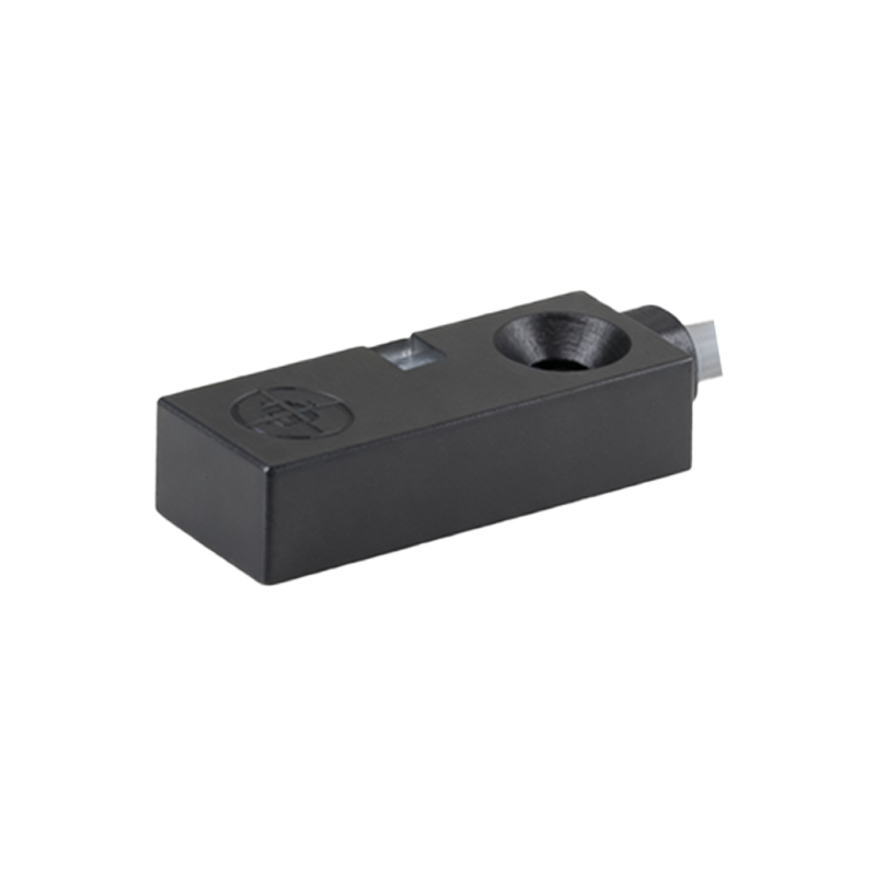
1. Output Type: This is the primary determinant. Electromechanical Relay Outputs have the most pronounced cycle limit, often in the range of 10 to 100 million operations. The life is constrained by mechanical wear of the contacts, spring fatigue, and contact erosion from arcing during switching. Solid-State Outputs (SSR), whether DC (transistor) or AC (triac), boast much higher theoretical cycle lives, often exceeding 100 million or even billions of cycles. Their limitation comes from thermal stress on the semiconductor junction during switching and gradual parameter drift.
2. Load Characteristics: The electrical load the sensor switches is paramount. Inductive loads (solenoids, relays, contactor coils) are particularly harsh. When switching off an inductive load, a high-voltage transient (back-EMF) is generated, causing arcing on relay contacts or stress on solid-state components. Inrush currents, common with lamps or capacitive loads, create a sudden surge of current that can weld relay contacts or damage semiconductors. Operating within the sensor's specified load current and voltage ratings is non-negotiable for achieving the published cycle life.
3. Switching Frequency: Continuously operating a sensor near its maximum switching frequency generates sustained internal heat. For solid-state sensors, excessive heat is the enemy of longevity, accelerating semiconductor aging. For relay types, high-frequency operation can lead to contact bounce and increased arcing. Derating the switching frequency or ensuring adequate thermal management can dramatically extend service life.
4. Environmental Conditions: Ambient temperature, humidity, vibration, and the presence of contaminants directly impact cycle life. High temperatures accelerate all failure mechanisms. Vibration can cause physical misalignment or contact chatter in relays. Dust, oil, and metallic shavings can infiltrate sensor housings, interfering with operation or causing short circuits. Selecting a sensor with an appropriate Ingress Protection (IP) rating for the environment is crucial.
5. Electrical Stress: Voltage spikes and surges on the supply lines, often from nearby large motors or switching events, can bypass protection circuits and damage the sensor's internal electronics, effectively ending its life prematurely. Using protective devices like surge suppressors or RC networks is a wise practice.
To maximize the cycle life of your proximity sensor switches, adhere to the following best practices:
Select the Correct Output Type: For high-speed, high-frequency applications (e.g., counting small parts), a solid-state PNP/NPN output is mandatory. For switching highly inductive or high-current loads where robustness to surges is key, a quality electromechanical relay output, possibly with external arc suppression, might be more suitable despite its lower cycle rating.
Understand and Respect the Load: Always consult the sensor's data sheet for load-specific derating curves. Use protective circuits: diode suppression for DC inductive loads, varistors or RC snubbers for AC loads.
Provide a Clean, Stable Operating Environment: Install sensors away from excessive heat sources and ensure proper mounting to minimize vibration. Use conduit or protective housings in dirty environments.
Implement Preventive Maintenance: Periodically check sensors for physical damage, cleanliness, and proper operation. Log operational hours or cycle counts where feasible to plan for proactive replacement before catastrophic failure causes downtime.
In conclusion, the switch cycle limit of a proximity sensor is not a fixed number but a guideline heavily dependent on application conditions. By understanding the underlying factors—output technology, load profile, switching frequency, and environment—engineers can make informed selection and application decisions. Prioritizing these considerations during the design phase ensures not only that the sensor meets its rated life