Photoelectric proximity sensors are critical components in modern industrial automation, offering non-contact detection capabilities for various applications. However, like any electronic device, they are susceptible to failures that can disrupt production lines and cause costly downtime. This guide provides a systematic approach to diagnosing and repairing common faults in photoelectric sensors, based on industry best practices and engineering expertise.
The first step in troubleshooting is to identify the symptoms. Common issues include intermittent detection, complete failure to detect objects, false triggering, or unstable output signals. Begin by checking the power supply, as voltage fluctuations or incorrect wiring are frequent culprits. Ensure the sensor is receiving the specified voltage (typically 10-30 VDC for DC models) and that the polarity is correct. Use a multimeter to verify the voltage at the sensor terminals, accounting for any voltage drops in the wiring.
Next, inspect the sensor's environment. Contamination such as dust, oil, or moisture on the lens can attenuate or scatter the light beam, leading to unreliable operation. Clean the lens gently with a soft, lint-free cloth and isopropyl alcohol. Additionally, consider ambient light interference, especially from strong sources like sunlight or welding arcs. Many sensors feature a modulated light source to mitigate this; ensure the modulation frequency is set appropriately and that the receiver is correctly synchronized.
Alignment is another critical factor. For through-beam sensors, misalignment between the emitter and receiver can cause detection failures. Use alignment tools or indicators (if available) to adjust the units precisely. For retro-reflective sensors, check the reflector for damage or misorientation. Diffuse sensors require careful consideration of the target's reflectivity and distance; consult the datasheet for the correct sensing range and adjust accordingly.
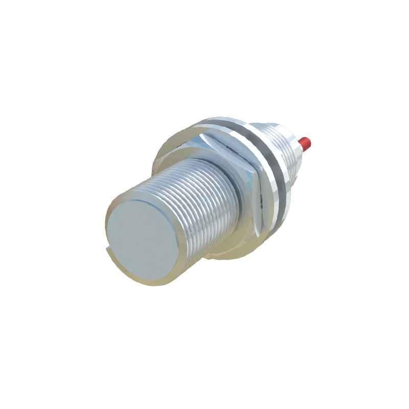
If environmental and alignment checks yield no issues, proceed to examine the sensor's internal components. Start with the output stage. For digital output sensors, monitor the output LED indicator (if present) and use an oscilloscope to check the signal integrity. A weak or noisy signal may indicate a failing output transistor or damaged circuitry. Analog output sensors should provide a linear response to distance; deviations may suggest potentiometer drift or amplifier faults.
In cases of physical damage, such as cracked housings or broken connectors, replacement is often the most cost-effective solution. However, for minor issues like loose internal connections, disassembly and re-soldering may be viable. Always follow electrostatic discharge (ESD) precautions when handling circuit boards. Note that some sensors are sealed and not user-serviceable; attempting repair could void warranties or cause further damage.
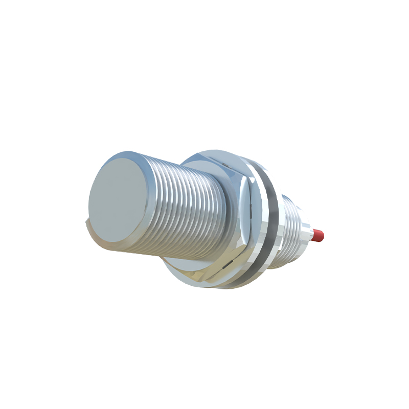
Preventive maintenance is key to minimizing failures. Regularly schedule cleaning and inspection routines. Implement environmental protections like enclosures or air purges in harsh conditions. Use surge protectors to guard against electrical transients, and ensure proper grounding to reduce electromagnetic interference. Log sensor performance data to identify trends or recurring issues, enabling proactive replacements before catastrophic failure.
Finally, consult the manufacturer's documentation for model-specific troubleshooting tips. Many modern sensors offer diagnostic features via IO-Link or similar interfaces, providing detailed status information that simplifies fault isolation. When in doubt, contact technical support with detailed observations, including sensor model, application details, and error symptoms, to expedite resolution.
By following this structured approach, engineers can efficiently restore sensor functionality, maintaining operational efficiency and reducing unplanned downtime in industrial settings.