Proximity switches and sensors are fundamental components in modern industrial automation, providing non-contact detection of objects without physical interaction. These devices are widely used for position sensing, object counting, speed monitoring, and safety applications across manufacturing, packaging, automotive, and material handling industries. Understanding their proper usage ensures reliable operation, enhanced system efficiency, and reduced downtime.
Proximity sensors operate based on different principles, primarily inductive, capacitive, and magnetic (reed or Hall effect). Inductive sensors detect metallic objects using an electromagnetic field, making them ideal for metal detection in machinery. Capacitive sensors can detect both metallic and non-metallic materials by sensing changes in capacitance, suitable for liquid level or plastic part detection. Magnetic proximity switches respond to permanent magnets, often used in cylinder position sensing. Selecting the correct type is the first critical step.
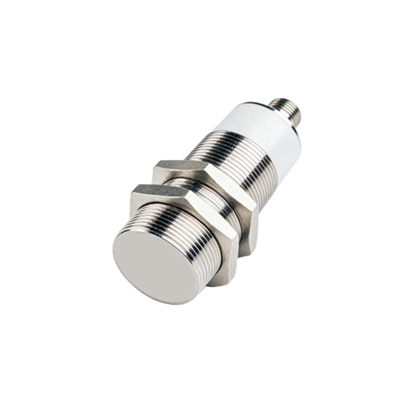
Installation and mounting require careful attention. Ensure the sensor is positioned correctly relative to the target object. The sensing distance, specified by the manufacturer, should be maintained with a safety margin to account for environmental factors like temperature fluctuations or vibration. Avoid mounting sensors near strong electromagnetic fields, welding equipment, or other sources of interference that could cause false triggering. For inductive and capacitive sensors, the target material, size, and approach direction affect performance; consult datasheets for correction factors.
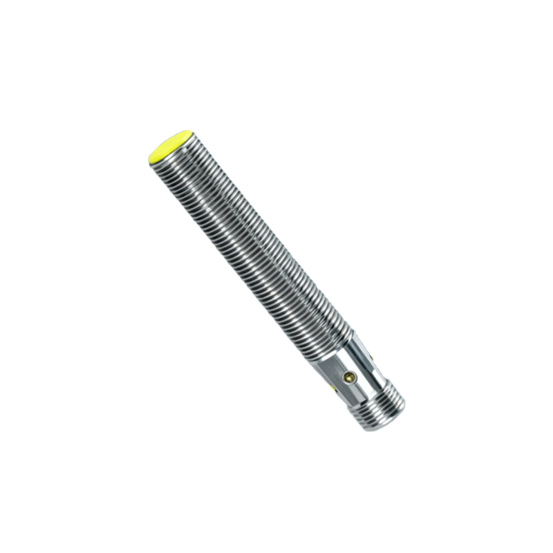
Wiring and electrical connections must adhere to safety standards and manufacturer guidelines. Most proximity sensors have three-wire configurations (DC versions: brown for +V, blue for 0V, black for output; AC versions may differ). Always verify voltage ratings (e.g., 10-30V DC or 90-250V AC) and load current limits to prevent damage. Use shielded cables in electrically noisy environments and ensure proper grounding. For two-wire AC/DC sensors, note that a residual current may flow even when off; this should be considered in control logic.
Configuration and adjustment involve setting parameters like sensitivity, hysteresis, and output mode. Many modern sensors feature teach-in functions or potentiometers for fine-tuning. Adjust sensitivity to avoid detecting unwanted objects (e.g., background materials). Hysteresis prevents output chattering when a target is near the detection threshold. Output types include normally open (NO), normally closed (NC), or analog (4-20mA, 0-10V), selected based on the control system requirements.
Integration with control systems, such as PLCs (Programmable Logic Controllers) or relays, requires matching signal levels. NPN (sinking) and PNP (sourcing) outputs are common in DC sensors; choose according to the input module type. For high-speed applications, check the sensor's response time to ensure it meets cycle demands. Regular maintenance, including cleaning sensing faces and checking for physical damage, prolongs service life. Diagnostic LEDs on sensors aid troubleshooting by indicating power status and output activation.
In summary, effective use of proximity switches involves correct selection, precise installation, proper wiring, and systematic integration. By following these practices, engineers can optimize automation systems for accuracy, safety, and longevity, minimizing operational disruptions.