In the realm of industrial automation and electrical system design, proximity sensors are indispensable components. Their ability to detect the presence or absence of an object without physical contact makes them crucial for countless applications, from assembly lines to safety systems. For electrical engineers and designers, the creation and interpretation of precise CAD (Computer-Aided Design) drawings for these sensors is a fundamental skill. This guide delves into the essential aspects of proximity sensor CAD drawings, outlining best practices, key elements, and industry standards.
The primary purpose of a proximity sensor CAD drawing is to provide a clear, unambiguous, and dimensionally accurate representation of the sensor for integration into a larger electrical or mechanical assembly. A well-constructed drawing serves multiple stakeholders: it guides the panel builder during installation, informs the procurement team for accurate sourcing, and aids maintenance personnel for future troubleshooting or replacement. The drawing must communicate not just physical form, but also critical functional interfaces.
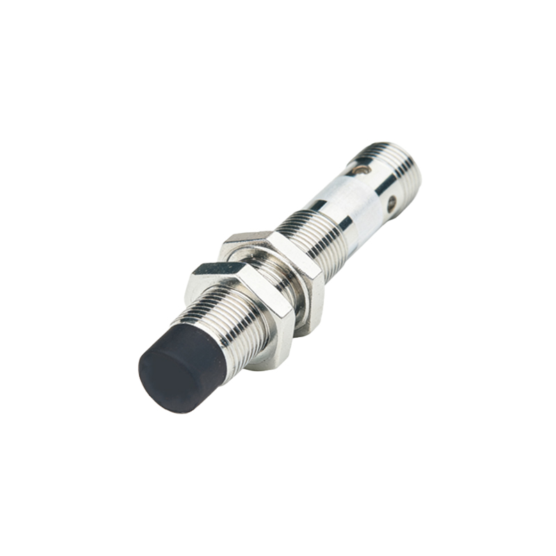
A standard proximity sensor CAD drawing package should include several key views and details. The orthographic projections (typically front, side, and top views) are non-negotiable. These views must include all critical dimensions: overall length, width, and height, thread size (e.g., M8, M12, M18, M30), sensing distance, and the exact location of mounting holes or brackets. For cylindrical inductive or capacitive sensors, detailed thread callouts with tolerances are paramount. Sectional views are highly recommended to illustrate internal components, such as the sensing face construction, LED indicator placement, and cable gland or connector entry points. This is vital for ensuring there is no interference with adjacent components in a crowded control cabinet or machine frame.
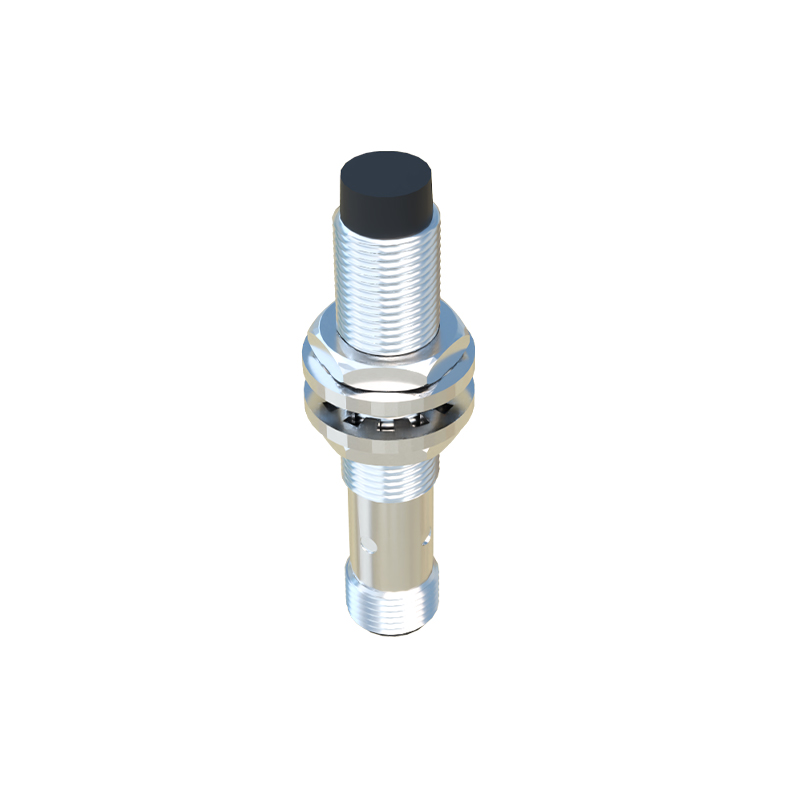
Electrical connection details form another critical layer of the drawing. While a separate schematic diagram will detail the circuit, the CAD drawing itself must accurately depict the connection interface. This includes the type of connector (e.g., M12 4-pin or 5-pin, Eurofast) or the cable outlet dimensions and strain relief mechanism. The pin assignment or cable core color code should be noted in a table on the drawing sheet. For sensors with built-in amplifiers or programmable features, the location and orientation of configuration switches or teach-in buttons should be clearly shown.
Material and finish specifications must be explicitly stated. Notes should indicate the housing material (e.g., stainless steel 316L, nickel-plated brass, PBT plastic) and the rating of the sensing face (often a wear-resistant material like PTFE or ceramic). Environmental protection ratings, according to IP (Ingress Protection) or NEMA standards, are crucial design parameters. A note such as "IP67" or "NEMA 6P" should be prominently displayed, as this directly impacts where the sensor can be deployed.
Adherence to international drafting standards is essential for universal comprehension. Whether following ISO 128 for general technical drawing principles or more specific regional standards, consistency is key. Layers should be logically organized (e.g., separate layers for outline, dimensions, hidden lines, notes). Line weights must differentiate between visible edges, hidden lines, and centerlines. All text should be legible and dimensioning should follow the aligned or unidirectional system consistently. A title block containing the part number, sensor model (e.g., E2E-X18MF1), revision history, company name, and scale is mandatory.
In modern practice, 3D models are integral. A detailed 3D model of the proximity sensor allows for interference checking within a full digital mock-up of the assembly. It enables the creation of accurate bill of materials (BOM) and facilitates simulation. The 3D model should be parametric where possible, allowing for easy generation of variant drawings for a sensor family. The 2D drawings are then often derived directly from this authoritative 3D model to ensure perfect synchronization.
Finally, consider the output and collaboration. Drawings should be saved in widely compatible formats like DWG, DXF, or STEP for 3D models. Including a PDF version for review and markup is a common industry practice. Always ensure that the latest revision of the drawing is centrally accessible to all project members to prevent costly errors from outdated documentation.
Mastering the details of proximity sensor CAD drawings elevates the quality, reliability, and maintainability of electrical designs. By meticulously defining form, fit, and function, these drawings become the silent language that ensures sensors perform their critical roles flawlessly within complex automated systems.