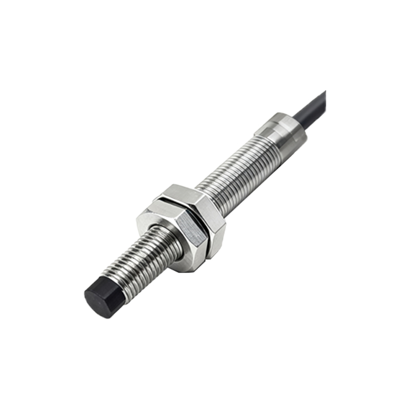
Inductive proximity sensors are non-contact electronic devices designed to detect the presence of metallic objects without physical contact. Their robust structure and reliable operation make them indispensable in industrial automation, machinery safety systems, and position sensing applications. Understanding the internal architecture of these sensors is key to appreciating their functionality and selecting the right model for a specific task.
At the heart of an inductive proximity sensor lies a coil wound around a ferrite core. This assembly forms the core of an oscillator circuit. When powered, this oscillator generates a high-frequency electromagnetic field that radiates from the active face of the sensor, typically made of a wear-resistant material like PTFE or nickel-plated brass. This field is the sensor's "sensing zone." The entire coil and core assembly is housed within a shielded or unshielded casing. Shielded sensors have a metal ring surrounding the coil, concentrating the field radially in front of the face, allowing for flush mounting in metal. Unshielded sensors have a more extended lateral sensing field but require non-metallic surroundings for installation.
When a metallic target enters this oscillating electromagnetic field, eddy currents are induced on the target's surface. These currents draw energy from the oscillator circuit, causing a reduction in the oscillation amplitude. A dedicated evaluation circuit within the sensor continuously monitors this amplitude. Once the amplitude drop exceeds a predefined threshold—corresponding to the sensor's nominal sensing distance—the circuit triggers a state change in the output stage.
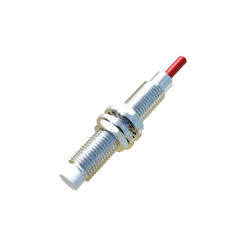
The output stage is another critical structural component. It can be a solid-state switch like an NPN or PNP transistor, or a relay in some older models. This switch controls the output signal, which is either a digital ON/OFF signal or, in analog versions, a current or voltage proportional to the distance. All these electronic components are potted in epoxy resin within a robust housing, usually made of stainless steel, brass, or industrial-grade plastic. This potting provides exceptional resistance to vibration, shock, and environmental contaminants like dust, coolants, and oils, ensuring longevity in harsh industrial settings.
The front end of the sensor often incorporates an LED status indicator. This visual feedback is crucial for diagnostics and setup, showing power status and the switching state when a target is detected. The electrical connection is made via pre-wired cables or quick-disconnect connectors, with options for various cable materials and lengths to suit different installation environments.
The performance is defined by its structure. Key specifications like sensing range, repeat accuracy, and switching frequency are directly influenced by the coil size, oscillator frequency, and circuit design. For instance, a larger coil diameter generally provides a longer sensing range. The housing material and ingress protection (IP) rating, such as IP67 or IP69K, determine its resilience against liquids and solids, defining its suitability for washdown areas or outdoor use.
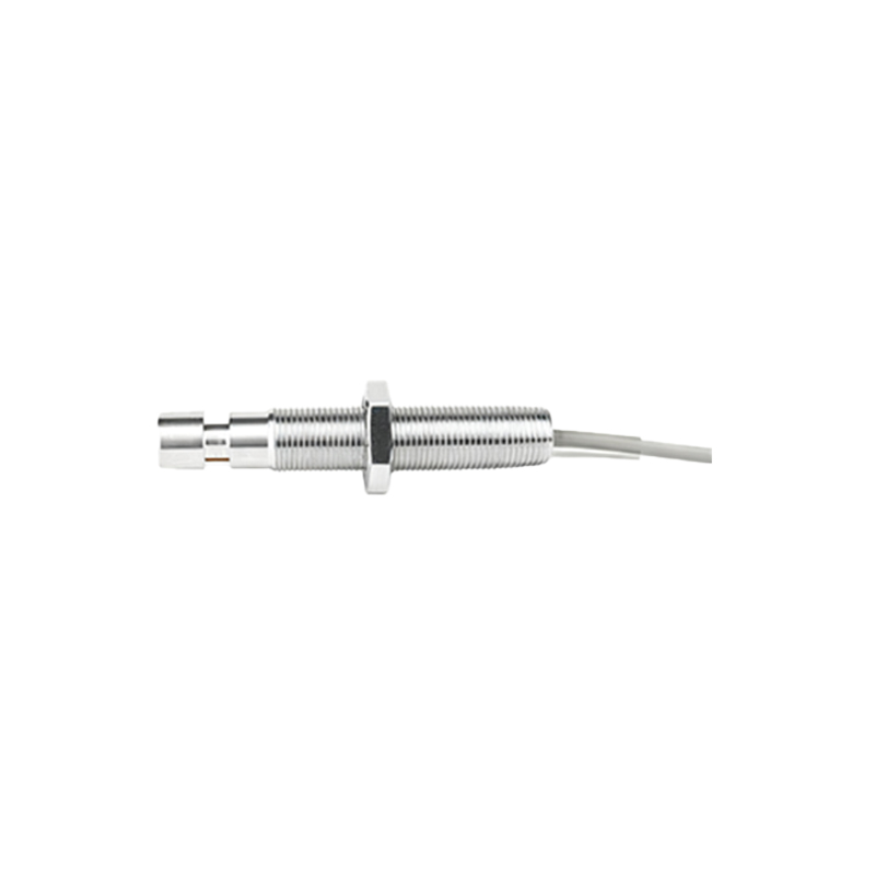
In summary, the inductive proximity sensor is a marvel of practical engineering. Its structure—from the internal ferrite core coil and sophisticated damping evaluation circuit to the ruggedized, potted housing—is meticulously designed to convert the physical phenomenon of electromagnetic induction into a reliable, maintenance-free switching signal. This simple yet effective design principle has cemented its role as a fundamental building block in automated systems worldwide.