Proximity sensors are critical components in industrial automation, robotics, and safety systems, relying on precise electromagnetic field generation to detect objects without physical contact. At the heart of these sensors lies the bobbin winding—a fundamental process that determines the sensor's sensitivity, range, and reliability. This article delves into the core principles, techniques, and best practices for winding bobbins in proximity sensor applications.
The bobbin, typically made from thermoplastic or thermosetting materials, serves as a structural support for the coil winding. Its design ensures consistent layering and alignment of the wire, which is crucial for maintaining a stable magnetic field. The winding process begins with selecting the appropriate wire gauge and insulation type, often polyurethane or polyester-coated copper wire, to withstand environmental stressors like moisture, temperature fluctuations, and chemical exposure.
Winding techniques vary based on sensor type—inductive, capacitive, or magnetic—but share common objectives: minimizing inter-turn capacitance, reducing electromagnetic interference (EMI), and achieving uniform winding density. For inductive proximity sensors, which are most common, the coil generates an oscillating electromagnetic field. When a metallic object enters this field, eddy currents are induced, altering the coil's impedance and triggering detection. The winding must be tightly controlled to ensure the field is consistent and directional.
Automated winding machines are standard in high-volume production, offering precision in tension control, layering, and termination. Key parameters include winding tension (typically 10–50 grams-force), wire feed speed, and the number of turns, which can range from 100 to over 2000 depending on the sensor's detection range. Overwinding or loose turns can lead to field distortion, reducing sensitivity and causing false triggers. Conversely, excessive tension may damage wire insulation, leading to short circuits or reduced lifespan.
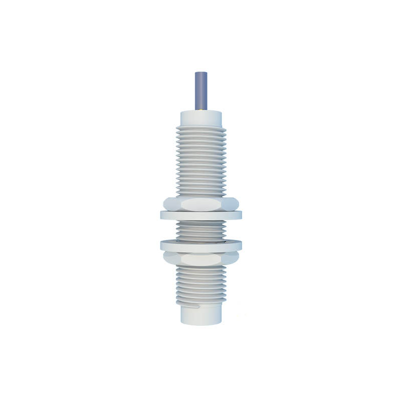
Layer winding and random winding are two primary methods. Layer winding involves orderly, stacked turns, which enhance magnetic field uniformity but require careful insulation between layers to prevent voltage breakdown. Random winding, while faster, may introduce air gaps that affect performance. In precision sensors, layer winding with insulating tape or varnish coating is preferred for stability.
Termination processes, such as soldering or welding the wire ends to lead pins, must ensure low-resistance connections to prevent signal loss. Post-winding, coils often undergo impregnation with epoxy or varnish to secure the windings, improve thermal conductivity, and protect against vibration and humidity. Quality checks include resistance measurement, inductance testing, and high-potential (hipot) tests to verify insulation integrity.
Advancements in materials, such as high-temperature-resistant bobbins and litz wire for high-frequency applications, continue to push the boundaries of sensor performance. Engineers must balance electrical requirements with mechanical constraints, ensuring the bobbin fits within the sensor housing without compromising the magnetic circuit.
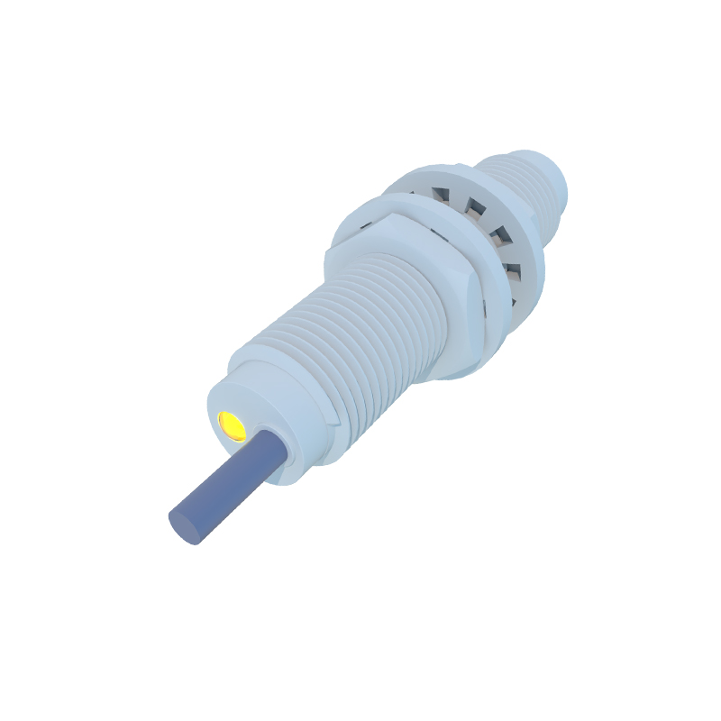
In summary, bobbin winding is a meticulous process that directly impacts proximity sensor efficacy. By adhering to precise winding protocols and leveraging modern manufacturing technologies, engineers can produce sensors with enhanced detection capabilities, durability, and consistency, meeting the rigorous demands of industrial environments.