Magnetic proximity sensors are widely used in industrial automation for detecting the presence or absence of ferrous metal objects without physical contact. Proper wiring is crucial for ensuring reliable operation, safety, and longevity of these sensors in demanding environments. This guide outlines the fundamental wiring principles, common configurations, and best practices for magnetic proximity sensors.
Most magnetic proximity sensors consist of two main components: a sensing head and an amplifier or evaluation unit. The sensing head, often a reed switch or magnetoresistive element, is typically installed on moving machinery or stationary fixtures, while the amplifier is mounted in a control cabinet. The connection between them is made via shielded cables to minimize electromagnetic interference (EMI).
Wiring configurations generally fall into two categories: two-wire and three-wire systems. Two-wire sensors are simpler, connecting in series with the load. They are often used in basic on/off applications but may have higher leakage currents. Three-wire sensors are more common in industrial settings, providing separate wires for power supply, ground, and output signal. The output can be either NPN (sinking) or PNP (sourcing), which must match the input type of the connected controller (PLC, relay, etc.). For NPN types, the load is connected between the output wire and positive voltage; for PNP, the load is between output and ground.
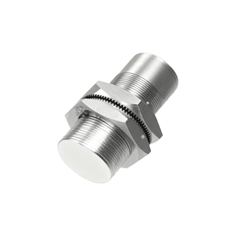
Power supply requirements must be strictly observed. Most DC magnetic proximity sensors operate within 10-30V DC. Incorrect voltage can lead to malfunction or permanent damage. Always refer to the manufacturer's datasheet for specific voltage and current ratings. Polarity is critical for DC sensors; reversing power wires can destroy the internal circuitry.
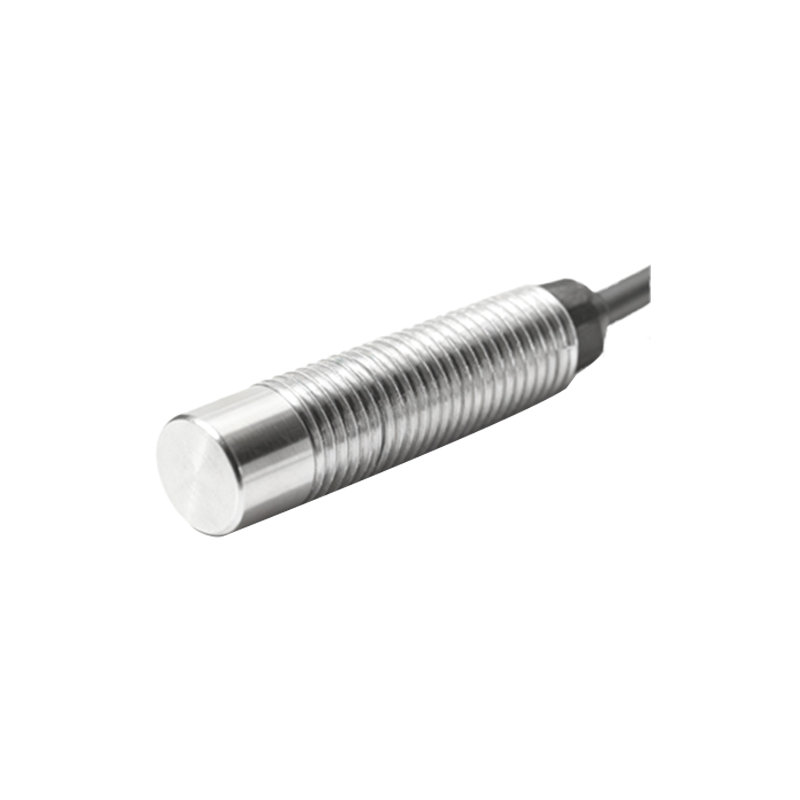
Shielding and grounding are essential for noise immunity. Use shielded cables, with the shield grounded at only one end—preferably at the control cabinet—to prevent ground loops. Keep sensor cables away from high-voltage power lines, motor drives, and other sources of electrical noise. Conduits or cable trays can provide additional physical and EMI protection.
For hazardous areas, intrinsically safe (IS) wiring practices are mandatory. This involves using approved barriers or isolators to limit energy to the sensor, preventing ignition of flammable atmospheres. All wiring must comply with local and international standards, such as IEC 60947-5-2.
Installation tips include ensuring proper sensing distance. Magnetic sensors have a specified operating distance; metal objects beyond this range may not be detected reliably. Avoid mounting sensors on vibrating surfaces unless they are specifically rated for such conditions. Environmental factors like temperature, humidity, and chemical exposure should also be considered—select sensors with appropriate IP (Ingress Protection) ratings.
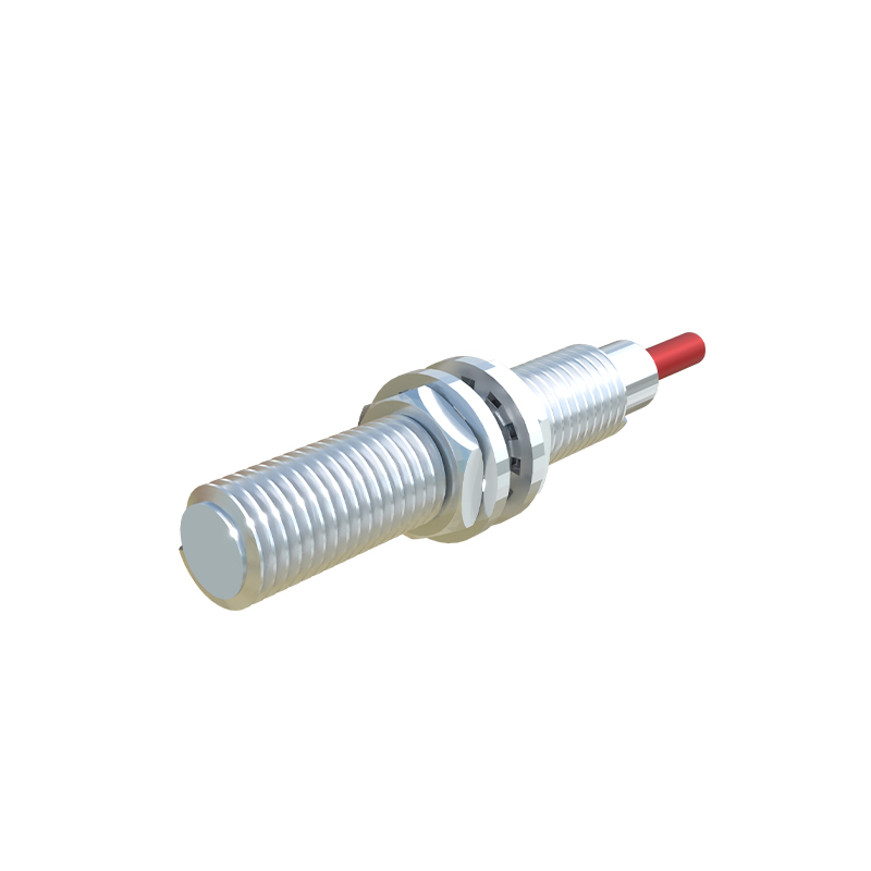
Testing and maintenance involve verifying output signals with a multimeter or oscilloscope. Regularly check for loose connections, cable damage, and corrosion. In three-wire systems, if the sensor fails, confirm power and ground integrity before replacing the unit.
In summary, correct wiring of magnetic proximity sensors enhances system reliability and safety. Always follow manufacturer guidelines, adhere to electrical codes, and consider the specific application demands for optimal performance.