In the realm of industrial automation and control systems, proximity sensors are indispensable components for non-contact detection of objects. A critical, yet sometimes overlooked, parameter defining their performance is the frequency response, often referred to as the switching frequency or response time. This characteristic directly dictates how swiftly and reliably a sensor can detect objects in high-speed applications, impacting overall system throughput and precision.
Defining Frequency and Response Time
The switching frequency of a proximity sensor is the maximum number of switching operations (ON/OFF cycles) it can perform per second, typically measured in Hertz (Hz). For instance, a sensor rated at 1 kHz can theoretically detect up to 1000 objects per second. This is intrinsically linked to the sensor's response time, which is the total time delay between a change in the sensing field (caused by a target entering or leaving) and the corresponding change in the output signal. Response time usually comprises two components: the approach time (target entering) and the release time (target leaving). A faster response time enables a higher achievable switching frequency.
Factors Influencing Sensor Frequency
Several key factors determine the operational frequency of a proximity sensor:
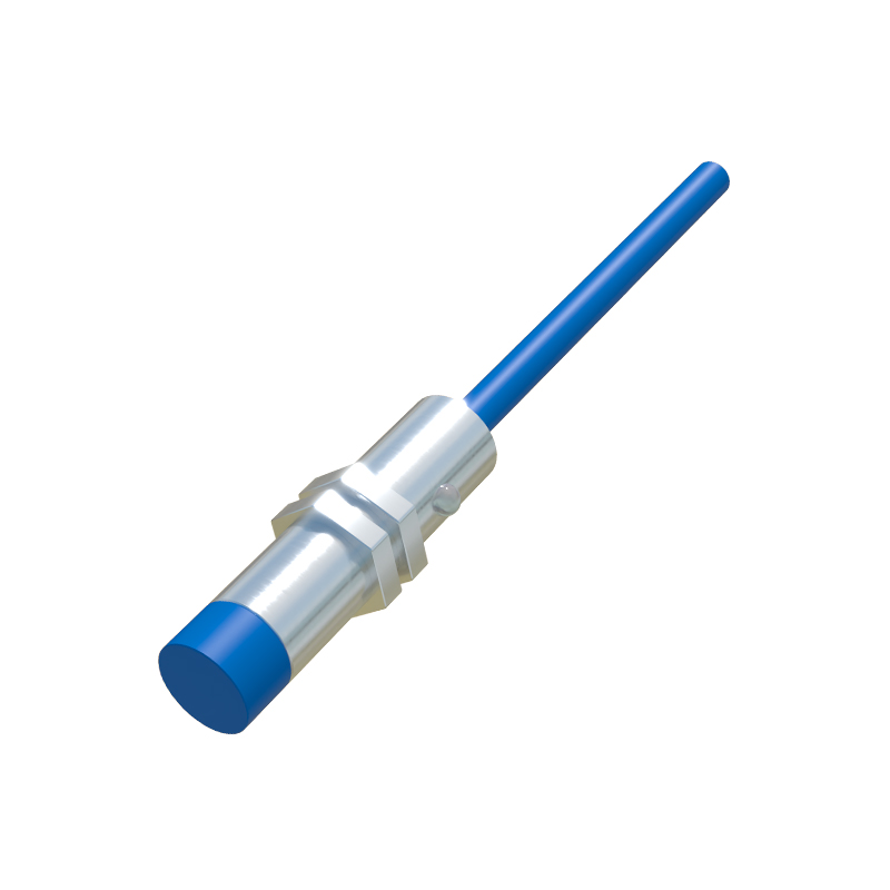
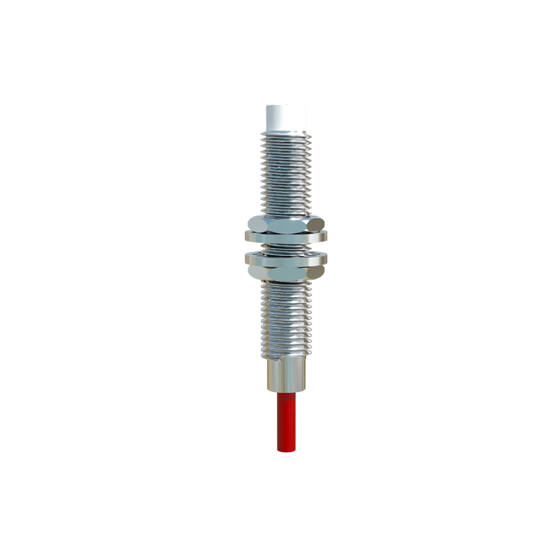
1. Sensor Technology: Different sensing principles have inherent speed limits. Inductive sensors (for metals) and capacitive sensors (for various materials) typically offer high frequencies, often ranging from 500 Hz to 5 kHz, with specialized models exceeding 10 kHz. Photoelectric sensors can achieve very high frequencies, sometimes up to 50 kHz, depending on their mode (through-beam, retro-reflective, diffuse).
2. Physical Design and Circuitry: The design of the oscillator coil (in inductive sensors), the quality of internal electronic components, and the signal processing algorithms significantly affect response speed. Shorter signal paths and advanced ASICs (Application-Specific Integrated Circuits) contribute to faster switching.
3. Target Characteristics: For inductive sensors, the size, material, and approach speed of the metal target are crucial. A larger, ferrous target (like mild steel) entering the sensing field optimally will yield the fastest response. Smaller targets or non-ferrous metals like aluminum may reduce the effective sensing distance and slightly increase response time.
4. Output Configuration: The type of output stage influences frequency. Standard DC 3-wire sensors with NPN or PNP transistor outputs generally offer higher frequencies than analog output versions or sensors with built-in relay outputs, which are mechanically slower.
5. Environmental Conditions: Extreme temperatures, strong electromagnetic interference (EMI), or voltage fluctuations can affect the stability and speed of the internal oscillator, potentially degrading the maximum reliable switching frequency.
Importance in Real-World Applications
Selecting a sensor with an appropriate frequency rating is vital for system integrity. Inadequate frequency response leads to missed counts or erroneous signals.
High-Speed Counting: On packaging lines counting bottles, cans, or small components, sensors must match the line speed. A 2 kHz sensor on a line producing 3000 items per minute (50 Hz per item) is sufficient, but a 10 kHz sensor provides a significant safety margin.
Position Verification and Sequencing: In automated assembly or robotic pick-and-place cells, sensors verify the presence or precise position of parts within milliseconds. Slow sensors create bottlenecks.
Synchronization and Control: On rotary encoders, cutting machines, or printing presses, sensors provide timing pulses. Their response time must be fast enough to ensure accurate synchronization without phase lag.
High-Speed Motion Detection: Detecting the teeth of a gear for speed measurement or monitoring fast-moving machinery parts demands sensors with very high frequency capabilities.
Calculating and Verifying Requirements
A simple calculation can help determine the required sensor frequency:
Required Frequency (Hz) = (Object Speed / Object Size)
Consider both the speed of the target and the smallest feature you need to detect. Always incorporate a safety factor of 1.5 to 2 times the calculated value to account for real-world variances, sensor aging, and less-than-ideal target approaches.
To verify performance, consult the sensor's datasheet, which should specify response time under standard conditions. Testing under actual operating conditions with the intended target is highly recommended. Use an oscilloscope to measure the actual delay between the target's edge and the output signal transition.
Optimization and Best Practices
To ensure optimal frequency performance:
Select a sensor with a frequency rating significantly higher than your minimum requirement.
Ensure proper installation, maintaining the recommended sensing distance. Avoid over-driving the sensor by placing the target too close, as this can sometimes cause oscillation or delay in the release time.
Use targets that are standard and sized appropriately for the sensor's rated sensing distance.
Provide a stable, clean power supply with adequate filtering to minimize electrical noise.