Hall effect proximity switches have become indispensable components in modern industrial automation, offering non-contact sensing capabilities with high reliability and long operational life. As a senior electrical engineer with extensive field experience, I will delve into the programming and integration aspects of these sensors, focusing on practical implementation in control systems.
The fundamental principle behind Hall effect sensors is based on the voltage generated when a current-carrying conductor is placed in a magnetic field. In proximity switch applications, this phenomenon is utilized to detect the presence or absence of a magnetic target. Programming these devices involves configuring parameters such as switching thresholds, hysteresis, output types, and response times to match specific application requirements.
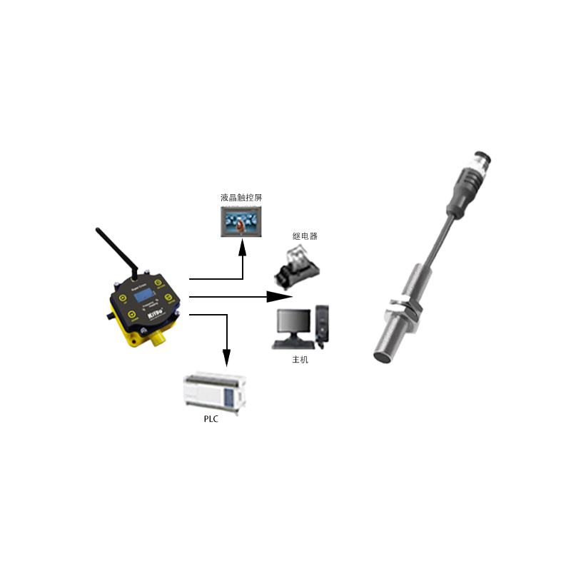
When integrating a Hall effect proximity switch into a programmable logic controller (PLC) system, the first step is to select the appropriate sensor type. Common variants include unipolar, bipolar, and omnipolar switches, each responding differently to magnetic pole orientations. Unipolar sensors activate in the presence of a south pole and deactivate when the magnetic field is removed, making them suitable for simple presence detection. Bipolar sensors respond to both north and south poles, often used in rotary encoding applications. Omnipolar sensors offer the flexibility of actuation by either pole, simplifying installation in complex machinery.
Wiring configuration is critical for reliable operation. Most industrial Hall effect switches provide three-wire connections: power supply, ground, and output. The output can be configured as NPN (sinking) or PNP (sourcing), depending on the PLC input module specifications. For instance, when connecting to a 24VDC PLC input, a PNP switch provides a positive voltage signal upon detection, while an NPN switch sinks current to ground. Incorrect wiring can lead to sensor damage or erratic system behavior, so always refer to manufacturer datasheets.
Programming the sensing parameters typically involves setting the operating point (Bop) and release point (Brp). The difference between these values, known as hysteresis, prevents output oscillation when the target is near the detection threshold. For high-speed applications, such as counting gear teeth or monitoring conveyor belt speeds, reducing hysteresis can improve response time but may increase susceptibility to electrical noise. Modern programmable Hall sensors allow adjustment via digital interfaces like IO-Link, enabling remote configuration and diagnostics without physical access to the sensor.
In automated production lines, Hall effect switches often interface with PLCs using ladder logic or structured text programming. A typical ladder rung might use an input contact from the sensor to trigger outputs, timers, or counters. For example, in packaging machinery, a Hall sensor detecting a metallic seal can increment a counter and activate a rejection mechanism if the count exceeds tolerances. Advanced programming techniques include using interrupts for high-priority events or implementing debounce logic in software to filter mechanical vibrations.
Environmental considerations play a significant role in programming decisions. Industrial environments expose sensors to temperature extremes, vibration, and electromagnetic interference (EMI). Programming fail-safe modes, such as latching the last known state or triggering an alarm upon signal loss, enhances system robustness. Additionally, many Hall sensors feature built-in diagnostics that can be monitored through PLC programs, providing predictive maintenance alerts for issues like weakened magnets or accumulated debris.
Calibration and testing are essential final steps. Using gaussmeters to measure magnetic field strength at the sensing face ensures consistent performance across multiple installations. In programming, simulate various operating conditions by moving targets at different speeds and distances to verify response accuracy. Document all parameters—including supply voltage, output configuration, and hysteresis settings—in maintenance manuals for future troubleshooting.
As Industry 4.0 advances, Hall effect proximity switches are increasingly integrated into networked systems. Through protocols like PROFINET or EtherNet/IP, sensors transmit real-time data to supervisory control and data acquisition (SCADA) systems, enabling centralized monitoring and optimization. Programming now extends beyond basic switching functions to include data logging, health reporting, and adaptive threshold adjustments based on machine learning algorithms analyzing operational trends.
In conclusion, mastering Hall effect proximity switch programming requires a blend of theoretical knowledge and practical expertise. By carefully selecting sensor types, configuring electrical and logical parameters, and implementing robust diagnostic routines, engineers can ensure reliable operation in demanding industrial applications. Continuous learning about emerging technologies, such as smart sensors with embedded intelligence, will further enhance the capabilities of automated systems in the digital era.