In the realm of industrial automation and machine design, the correct installation and orientation of proximity sensors are critical for reliable operation. A common point of discussion among electrical engineers and maintenance technicians is whether a sensor should be mounted in a front-facing or rear-facing orientation relative to the target. The answer is not universal and hinges on the sensor's technology, its specific design, and the application's environmental constraints. This article delves into the technical considerations to guide optimal sensor placement.
Fundamentally, a proximity sensor detects the presence or absence of an object within its sensing field without physical contact. The primary technologies include inductive, capacitive, ultrasonic, and photoelectric sensors. Each type generates a specific field or beam pattern, which is directional. The "front" of the sensor is universally defined as the side from which this sensing field emanates. This is typically marked on the sensor housing and is where the active face or lens is located. Therefore, for detection to occur, the target must approach this active front face. Mounting a sensor with its rear facing the target would render it ineffective, as the sensing field is not projected from that side.
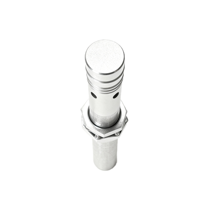
The core of the orientation debate, therefore, shifts from "front vs. rear" to the angular orientation of the sensor's front face relative to the target's path of travel and the surrounding machinery. Key considerations include:
1. Sensing Range and Field Shape: Inductive sensors, for detecting metals, have a hemispherical or cylindrical sensing field extending from the front face. The effective sensing distance is specified for a standard target approaching head-on (axially). Off-axis mounting or an angular approach reduces the effective operating distance. Photoelectric sensors, especially diffuse types, have a more conical beam. Their orientation must ensure the beam intercepts the target reliably, considering possible misalignment.
2. Target Characteristics: The size, material, and approach velocity of the target are paramount. For a small target, a head-on (frontal) approach is often necessary to ensure sufficient signal strength. For a large target, such as a metal plate, a side-mounted sensor with its front face parallel to the direction of travel (a "lateral" sensing mode) can be effective and may save space.
3. Environmental Protection and Physical Stress: Often, the decision to use a non-standard mounting angle is driven by the need to protect the sensor's active face. In environments with flying debris, weld spatter, or high-pressure washdown, mounting the sensor in a recess or at an angle can shield the front face. Some sensors are equipped with protective baffles or are specifically designed with a "side-looking" geometry, where the sensing field exits from the side of the cylindrical housing rather than the tip. This is sometimes colloquially called "rear mounting," but technically, the active face is still oriented toward the target—it's just located on the side of the body.
4. Installation Constraints and Interference: Space limitations within a control panel or machine frame may dictate orientation. A long, cylindrical inductive sensor might be mounted horizontally instead of vertically purely for mechanical fit. However, engineers must be cautious of mutual interference when mounting multiple inductive sensors in close proximity. Manufacturers specify minimum separation distances, which can vary if sensors are mounted side-by-side versus face-to-face. Incorrect orientation can lead to crosstalk and false triggering.
5. Mounting Hardware and Adjustability: Many sensors come with adjustable mounting brackets that allow fine-tuning of the angle post-installation. This is crucial for aligning photoelectric beams or tuning capacitive sensors to ignore a background material. The ability to pivot the sensor's front face a few degrees can mean the difference between a stable and an erratic system.
In summary, the question is not about using the sensor's non-sensing rear for detection, which is impossible, but about optimizing the spatial orientation of its active front face. Best practice involves:
Consulting the sensor datasheet for field diagrams, range specifications under different approach directions, and mounting clearances.
Creating a mock-up or using CAD models to visualize the sensor's field in relation to the target's path.
Considering environmental factors that may necessitate an angled mount for protection.
Allowing for physical adjustability during commissioning.
For instance, a thru-beam photoelectric sensor must have its emitter and receiver lenses facing each other directly. An ultrasonic sensor might be angled slightly downward to detect material in a bin while ignoring the opposite wall. An inductive sensor might be mounted with its side (if it is a side-sensing model) facing a conveyor to detect the edge of a metal sheet.
Ultimately, declaring a sensor "front" or "rear" mounted is a simplification. The professional approach is to specify its installation by defining the vector of its sensing axis relative to machine coordinates. Proper orientation