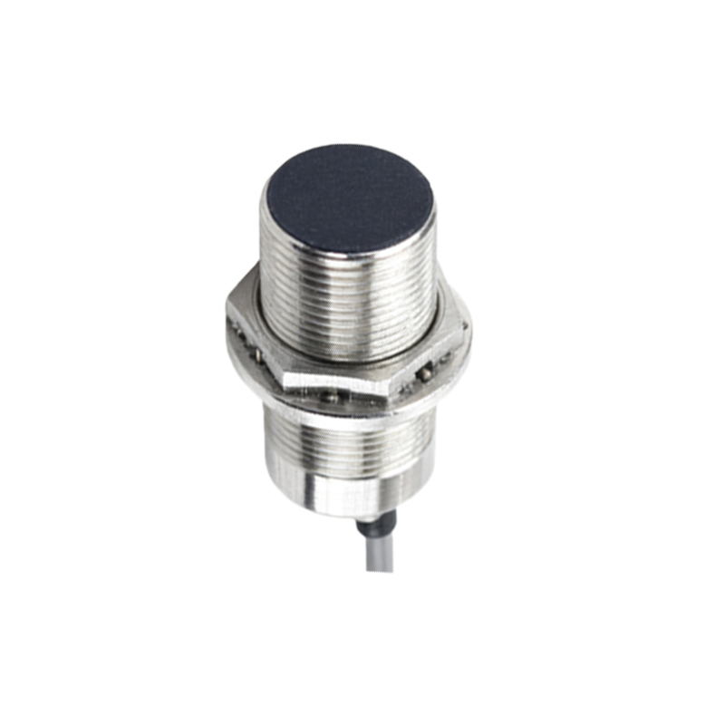
In the realm of industrial automation, proximity sensors are indispensable components for non-contact detection of metallic or non-metallic objects. While much attention is given to their sensing range, output types, and environmental ratings, a critical aspect often requiring deeper understanding is the sensor's load characteristic. This refers to the electrical load the sensor's output circuit is designed to drive, directly impacting system reliability, longevity, and performance.
Fundamentally, a proximity sensor's output stage acts as a switch. For DC sensors, this is typically a solid-state transistor (PNP or NPM sourcing/sinking). For AC/DC or AC sensors, it's often a triac or relay output. The load is the device being controlled—a programmable logic controller (PLC) input, a relay coil, a solenoid valve, an indicator lamp, or a small motor starter. Exceeding the sensor's specified load capacity is a primary cause of premature failure.
Key load parameters are clearly defined on every sensor datasheet. The maximum load current is the foremost limit. For a standard DC 3-wire sensor, this might be 200mA. Connecting a solenoid drawing 300mA will cause excessive heat buildup in the sensor's output transistor, leading to thermal degradation and eventual short-circuit failure. Conversely, operating significantly below the minimum load current (if specified) can also cause issues, as some solid-state outputs require a minimum current flow to stabilize.
Load voltage is equally crucial. A sensor rated for 10-30V DC must operate within that range. Applying 24V to a 10-30V sensor is fine, but applying 36V will likely damage the output circuitry. For AC sensors, the voltage and frequency (e.g., 90-250V AC, 50/60Hz) must be strictly observed. Inrush current is a particularly insidious load characteristic. Inductive loads like relay coils or solenoids can draw a current surge 5 to 10 times their steady-state value when first energized. A sensor rated for 200mA steady-state may not withstand a 2A inrush. This often necessitates derating—using a sensor with a higher current rating or adding protective components like inrush current limiters or RC snubber networks across the load.
Leakage current is a vital consideration for AC and AC/DC 2-wire sensors. When in the "OFF" state, a small current (typically 1-3mA) still flows through the sensor to power its internal electronics. If this leakage current exceeds the minimum operating current of the connected load (e.g., a highly sensitive PLC input module), it can cause the load to remain partially activated or "phantom trigger." Using a bleeder resistor (or load resistor) in parallel with the load can often solve this by providing a path for the leakage current, ensuring it drops below the load's activation threshold.
Proper load matching involves systematic calculation. First, identify the load's electrical characteristics: its steady-state operating current/voltage, its nature (resistive like a lamp, or inductive like a coil), and its inrush current. Second, compare these values against the sensor's rated switching capacity, ensuring all parameters are within limits with a safety margin (e.g., 20-30% headroom on current). For inductive loads, always refer to the sensor's specific rating for switching inductors, as it may differ from the resistive load rating.
In complex setups, interface relays are a robust solution. Instead of driving a large load directly, the proximity sensor switches a low-power relay coil, and the relay's contacts, rated for higher currents, control the primary load. This isolates the sensitive sensor electronics from potential voltage spikes, back-EMF from inductive loads, and high-current stress, dramatically enhancing system durability.
Understanding and respecting proximity sensor load characteristics is not merely a technical detail but a cornerstone of designing resilient and fail-safe automation systems. Meticulous load verification during the design phase prevents field failures, reduces downtime, and ensures the seamless, long-term operation that modern industrial processes demand. Always consult the manufacturer's datasheet as the ultimate authority for specific load connection guidelines and derating curves under various conditions.