In the realm of industrial automation and control systems, proximity sensors are indispensable components for detecting the presence or absence of objects without physical contact. Among their critical performance parameters, delay time—encompassing both response time and release time—stands as a pivotal factor influencing system efficiency, precision, and reliability. This article delves into the technical intricacies of proximity sensor delays, exploring their causes, implications, and optimization strategies from an engineering perspective.
Fundamentally, the delay time of a proximity sensor refers to the interval between the occurrence of a detection event and the corresponding change in the sensor's output signal. This latency is not instantaneous due to inherent physical and electronic processes. Response time is the duration from when a target enters the sensing range to when the output switches states. Conversely, release time is the period from when the target leaves the sensing zone to when the output reverts to its original state. These values are typically specified in milliseconds (ms) or microseconds (µs) within sensor datasheets and are influenced by several core factors.
The underlying sensing technology plays a primary role. Inductive sensors, detecting metallic objects, and capacitive sensors, detecting various materials, rely on changes in an oscillating circuit. The time required for this oscillation to build up or decay contributes directly to the delay. Photoelectric sensors, using light beams, involve the processing time of the received light signal by the phototransistor and amplifier circuitry. Ultrasonic sensors face delays related to the time-of-flight calculation of sound waves. Each technology has a characteristic delay profile; for instance, high-speed inductive sensors can achieve response times below 100 µs, while some ultrasonic sensors may have delays in the tens of milliseconds.
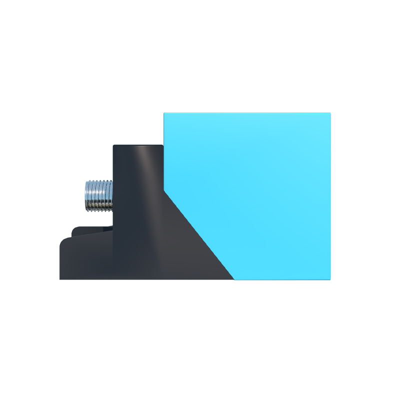
Circuit design and signal processing are equally crucial. Internal components like oscillators, amplifiers, comparators, and output stages (e.g., NPN/PNP transistors or solid-state relays) introduce switching delays. Manufacturers implement filtering algorithms to suppress electrical noise from variable frequency drives (VFDs), welding equipment, or electromagnetic interference (EMI). While essential for stability, this filtering—often adjustable via potentiometers or digital settings—adds to the overall delay. A trade-off exists: heavier filtering increases noise immunity but lengthens delay, whereas lighter filtering reduces latency at the risk of false triggering.
The physical properties of the target and its operational environment further modulate delay. For inductive sensors, the target material's conductivity and permeability affect the eddy current generation speed. The size, shape, and approach angle of the target relative to the sensor face can alter the effective sensing field interaction. Environmental extremes, such as high or low temperatures, can affect semiconductor performance within the sensor, potentially increasing response times. Additionally, the sensor's own design, including its sensing range and whether it is shielded or unshielded, influences the signal's behavior.
The consequences of improperly accounting for sensor delay are significant in high-speed or precision applications. In automated assembly lines, excessive delay can cause mis-timed robotic pick-and-place operations, leading to defects or jams. On packaging machinery, it might result in incorrect product counting or sealing. In safety-critical applications like light curtains or machine guarding, minimal delay is paramount to ensure rapid shutdown. Engineers must calculate the total system response time, incorporating sensor delay, controller scan time, and actuator response, to ensure it is shorter than the allowable time for a safe or correct operation.
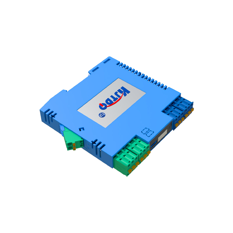
Optimizing and selecting sensors for appropriate delay involves a systematic approach. First, define the application's speed requirement. Calculate the maximum permissible delay based on the fastest-moving object or the shortest process window. When selecting a sensor, scrutinize the datasheet for typical and maximum response/release times under specified conditions (voltage, temperature, target). Consider sensors with adjustable response time or filtering, allowing fine-tuning on-site. For ultra-high-speed applications, explore specialized models marketed as "fast-response" or "high-speed." Implementing proper installation techniques—such as ensuring correct alignment, avoiding sensing field encroachment by metal backgrounds, and using shielded cables in noisy environments—can prevent conditions that exacerbate effective delay.
Furthermore, system integration practices can mitigate the impact of sensor latency. Using programmable logic controllers (PLCs) with fast input modules and optimizing program scan cycles are complementary measures. In some scenarios, employing predictive algorithms or installing sensors at a calculated lead distance can compensate for known delays. Regular maintenance, including cleaning the sensor face and checking for mechanical wear or loose connections, ensures sustained performance.

In conclusion, proximity sensor delay time is a multifaceted parameter rooted in sensor physics, electronics, and application dynamics. It is not a defect but a characteristic to be meticulously understood and managed. A profound comprehension of its origins enables engineers to make informed sensor selections, implement robust system designs, and troubleshoot performance bottlenecks effectively. By balancing speed, noise immunity, and reliability, optimal delay management becomes a cornerstone of achieving seamless, efficient, and precise industrial automation.
SEO