In industrial automation and precision manufacturing, laser head sensors play a critical role in ensuring accuracy, quality control, and operational efficiency. These sensors are integral components in systems such as laser cutting, engraving, 3D scanning, and alignment tools. When a laser head sensor malfunctions, it can lead to costly downtime, production errors, and safety risks. This guide provides a systematic approach for engineers and technicians to diagnose and address common issues with laser head sensors, emphasizing practical steps and industry best practices.
The first step in troubleshooting is recognizing the symptoms of a faulty sensor. Common indicators include inconsistent measurement readings, failure to detect targets, erratic beam alignment, or complete system shutdowns with error codes related to sensor communication. In laser cutting machines, for instance, a degraded sensor may cause imprecise cuts or material damage. For 3D scanners, it might result in distorted point clouds or scanning failures. Before assuming the sensor itself is defective, it's essential to rule out external factors. Begin by inspecting the operational environment: check for excessive dust, debris, or moisture that could obstruct the sensor's lens or emitter. Industrial settings often accumulate contaminants that interfere with optical components. Clean the sensor's surface gently using approved lens cleaners and compressed air, ensuring no scratches or permanent damage occur.
Next, examine the electrical and connectivity aspects. Verify all cable connections between the sensor, controller, and power supply. Loose or corroded connectors are frequent culprits behind intermittent failures. Use a multimeter to test voltage levels at the sensor's input terminals, comparing them against the manufacturer's specifications. Power fluctuations or insufficient current can cause sensor instability. Additionally, inspect the wiring for signs of wear, fraying, or electromagnetic interference from nearby high-voltage equipment. Shielding cables or rerouting them away from interference sources may resolve noise-related issues.
If physical and electrical checks yield no problems, proceed to software and calibration diagnostics. Many modern laser systems integrate sensors with programmable logic controllers (PLCs) or dedicated software interfaces. Access the system's diagnostic menu to review error logs, sensor status reports, and calibration data. Recalibrate the sensor according to the manufacturer's guidelines, as misalignment or drift over time can mimic hardware failure. For triangulation or time-of-flight sensors, ensure that reference distances and environmental parameters (e.g., temperature compensation) are correctly configured. Updating firmware or drivers might also address compatibility bugs or performance glitches.
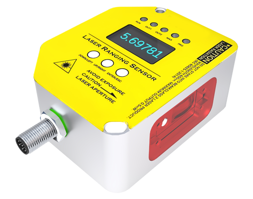
Should these steps fail to restore functionality, the sensor may have internal damage. Common hardware failures include degraded laser diodes, faulty photodetectors, or damaged internal circuitry. In such cases, consult the sensor's technical datasheet to identify test points for signal output. Using an oscilloscope, measure the sensor's output waveform under typical operating conditions. A weak or absent signal often confirms component failure. For modular sensors, consider replacing sub-components like emitter modules or receiver boards if available. However, many industrial laser head sensors are sealed units designed for replacement rather than repair.
When replacement is necessary, select a compatible sensor model that meets the original specifications for wavelength, accuracy, response time, and environmental ratings. Document the removal process carefully, noting cable orientations and mounting positions. Install the new sensor, ensuring proper mechanical alignment and secure fastening. After installation, recalibrate the entire system and conduct a series of test runs to verify performance. Implement preventive maintenance schedules to extend sensor lifespan, including regular cleaning, periodic recalibration, and environmental monitoring.
In summary, addressing a faulty laser head sensor requires a methodical approach: identify symptoms, eliminate external factors, check connections and power, perform software diagnostics, test hardware components, and replace if needed. By adhering to these protocols, engineers can minimize downtime and maintain the precision essential for industrial applications. Always prioritize safety by powering down equipment during inspection and following lockout-tagout (LOTO) procedures to prevent accidents.