Temperature drift is a critical, yet often overlooked, phenomenon in the performance of laser sensors. It refers to the change in a sensor's output signal caused by variations in ambient or internal operating temperature, independent of the actual measured parameter. For precision applications in industrial automation, metrology, and scientific research, uncompensated temperature drift can lead to significant measurement errors, reduced repeatability, and compromised system reliability. This article delves into the mechanisms of temperature drift in laser sensors, its practical implications, and effective strategies for mitigation.
The core of a laser sensor, particularly for distance or displacement measurement, often relies on optical triangulation, time-of-flight, or interferometric principles. Key components such as the laser diode, photodetector, and associated signal processing electronics are inherently sensitive to temperature. The wavelength of the laser diode itself shifts with temperature due to changes in the bandgap energy of the semiconductor material—a phenomenon described by the temperature coefficient of the wavelength. This shift can directly affect the calibration of interferometric systems or the focus in triangulation setups. Similarly, the responsivity and dark current of photodetectors (e.g., CCDs, CMOS, or PSDs) vary with temperature, altering the output signal for a given light input. Furthermore, passive optical elements like lenses can experience thermal expansion, subtly changing focal lengths and optical paths.
The consequences of temperature drift are not merely theoretical. In a coordinate measuring machine (CMM), a drift of a few micrometers over a 10°C temperature change can render high-tolerance part inspection invalid. In semiconductor lithography, sub-nanometer stability is required, making temperature control paramount. Even in seemingly robust environments like welding robots, where laser sensors guide seam tracking, ambient heat can induce drift, leading to faulty welds. The error is often non-linear and can exhibit hysteresis, meaning the sensor's output at a given temperature depends on whether the temperature is rising or falling, complicating simple correction.
Mitigating temperature drift requires a multi-faceted approach, starting at the sensor design stage. Manufacturers employ several techniques:
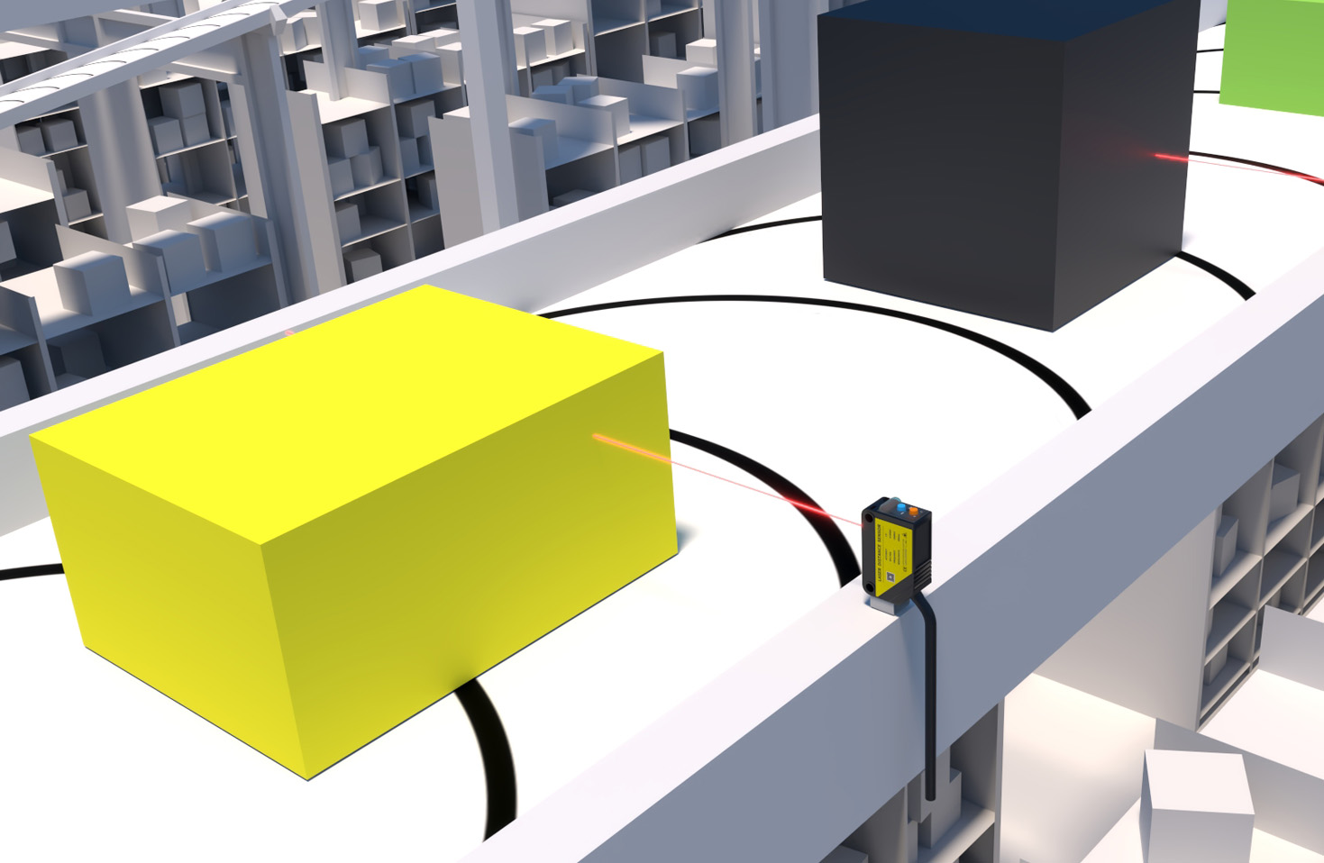
1. Component Selection and Thermal Design: Choosing laser diodes and detectors with lower inherent temperature coefficients is fundamental. Advanced packaging designs aim to dissipate heat efficiently, often incorporating thermal sinks or Peltier coolers for critical components to maintain a stable internal temperature.
2. Internal Reference and Compensation: Many high-end sensors integrate internal reference channels or temperature sensors (thermistors, RTDs) directly on the ASIC or near sensitive optics. The measured temperature is used to apply a correction algorithm to the output signal. This compensation curve is characterized during factory calibration across the sensor's specified operating temperature range.
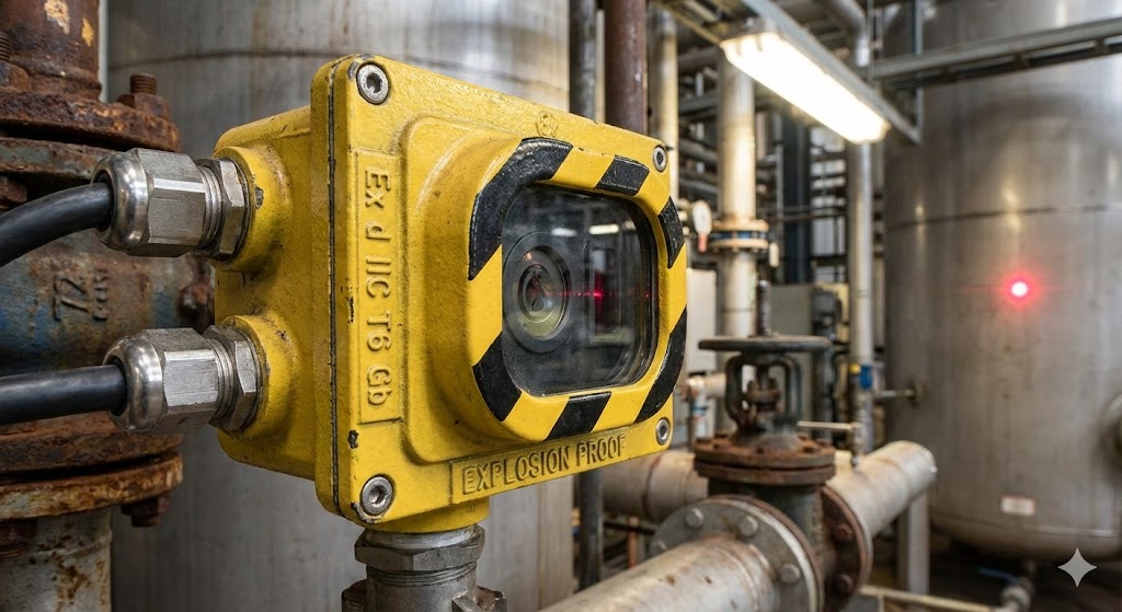
3. Stable Drive Circuits: Constant current drivers for laser diodes with feedback loops help stabilize optical power output against temperature-induced resistance changes. Similarly, temperature-stable amplifiers and analog-to-digital converters are crucial for the signal chain.
4. Algorithmic Compensation: Beyond hardware, sophisticated firmware implements real-time compensation models. These models can account for not just the sensor head temperature but also the temperature of the target surface, if known, as it can affect reflectivity and thermal expansion of the measured object.

For the end-user, understanding the sensor's datasheet specifications is vital. Key parameters to evaluate include: Temperature Coefficient (e.g., µm/°C or % of reading/°C), Operating Temperature Range, and Long-Term Stability. It is imperative to note whether accuracy specifications are valid over the entire temperature range or only at a fixed reference temperature (typically 20°C or 25°C).
Best practices in system integration are equally important. Avoiding placement near heat sources (motors, drives, processors), ensuring adequate airflow, and allowing sufficient warm-up time for the sensor electronics to reach thermal equilibrium can drastically reduce drift-related errors in the field. For the most demanding applications, operating the entire system in a temperature-controlled enclosure remains the gold standard.
In conclusion, temperature drift is an intrinsic challenge in laser sensing technology, rooted in the physics of semiconductors and materials. While modern sensors incorporate advanced compensation techniques, achieving optimal performance requires a synergistic effort between robust sensor design, careful selection based on application-specific needs, and intelligent system integration. Acknowledging and proactively managing thermal effects is not an option but a necessity for unlocking the full precision and reliability potential of laser sensors in today's high-stakes technological landscape.