In industrial automation and machinery design, the positioning of proximity sensors is a critical factor that directly impacts system reliability, accuracy, and longevity. These non-contact devices, which detect the presence or absence of an object within their sensing field, are deceptively simple. However, their effectiveness is entirely dependent on correct installation and placement. A sensor with excellent specifications can yield poor results if mounted incorrectly, leading to false triggers, missed detections, and costly downtime.
The foundation of good sensor positioning begins with a thorough understanding of the sensor's technology. Inductive sensors detect metallic objects, capacitive sensors detect both metallic and non-metallic materials, and photoelectric sensors use light beams. Each type has a unique sensing field pattern—be it cylindrical, conical, or rectangular. The first rule is to always consult the manufacturer's datasheet for the exact shape and size of the active sensing area. Never assume. The rated sensing distance (Sn) is specified under ideal conditions with a standard target. Real-world performance, known as the effective operating distance, can be reduced by factors like target material, size, temperature, and surrounding metal.
For inductive proximity sensors, the target material is paramount. Mild steel provides the full rated sensing distance. For stainless steel, expect a reduction of 10-30%, and for non-ferrous metals like aluminum or copper, the reduction can be 40-60%. Therefore, the sensor must be positioned closer to these materials. The target should also be large enough to fully enter the sensor's active face. A small bolt head may not be detected at the full distance where a large metal plate would be. The optimal approach is for the target to move directly toward the active face, not across it tangentially.
Environmental considerations are equally crucial. Inductive sensors can be affected by nearby metal, a phenomenon called "metal-in-ground." Mounting a sensor in a steel bracket or too close to other machine frames can diminish its sensing range or cause instability. A general guideline is to maintain a clearance of at least one to two times the sensor barrel diameter from surrounding metal. For sensors mounted flush with metal, ensure they are specifically designed for "flush mounting." Non-flush mount sensors require a free zone around their sensing face.
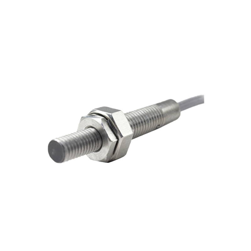
For capacitive sensors, which are sensitive to material density and dielectric constant, positioning is often about tuning and isolation. They can be influenced by humidity, dust, or unintended background objects. Mount them away from large stationary objects or material streams that could cause constant activation. Many feature a sensitivity potentiometer; position the sensor initially at a greater distance and adjust the sensitivity until it reliably detects the target while ignoring the background.
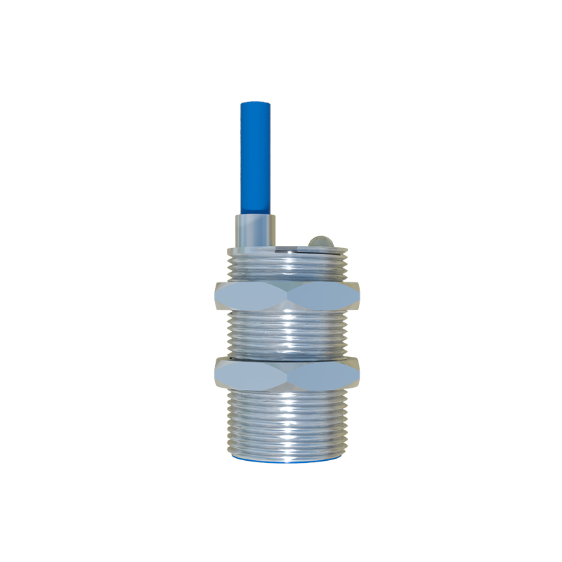
Photoelectric sensors present their own set of positioning rules. For through-beam types (separate emitter and receiver), precise alignment is critical. The units must be rigidly mounted to prevent vibration from breaking the beam. For reflective types, the angle of incidence must be considered. The target should approach in a way that reflects the beam directly back to the receiver. Avoid placing these sensors where ambient light (like sunlight or welding arcs) can flood the receiver. Polarized filters can help with shiny targets, but correct angular positioning is the primary defense against false reflections from glossy surfaces.
Universal best practices include securing the sensor against vibration using proper locknuts or brackets. Vibration can loosen mounts and change critical alignment. Consider the target's speed and the sensor's response time; the sensor must be positioned with enough lead distance to allow its signal to be processed before a mechanical action is required. For example, detecting a part on a fast conveyor to trigger a reject arm downstream. Always plan for maintenance access. A perfectly positioned sensor is useless if an operator cannot reach it for cleaning or verification.
Finally, rigorous testing under all possible operating conditions is non-negotiable. Test with the actual target material, at temperature extremes, and during machine startup and shutdown cycles. Monitor the sensor's output over an extended period to catch any intermittent issues. Proper positioning is not a one-time setup but a deliberate engineering decision that balances theoretical specifications with practical application realities. By methodically addressing material, environment, alignment, and dynamics, engineers can ensure proximity sensors deliver the robust, fail-free performance that modern automated systems demand.