Eddy current proximity sensors represent a critical category of non-contact measurement devices widely employed in industrial automation, aerospace, and manufacturing. Their fundamental operation relies on electromagnetic induction. At the heart of the system lies a sensor coil, which forms part of a resonant circuit, typically an LC oscillator. When an alternating current passes through this coil, it generates a high-frequency electromagnetic field around the probe's active face.
When a conductive target object enters this alternating magnetic field, eddy currents are induced on the target's surface. These circulating currents, according to Lenz's Law, generate their own opposing magnetic field, which interacts with the primary field from the coil. This interaction results in a change in the impedance of the sensor coil. The key measurable change is often a reduction in the amplitude of the oscillator's oscillation or a shift in its resonant frequency, as energy is dissipated into the target via the eddy currents.
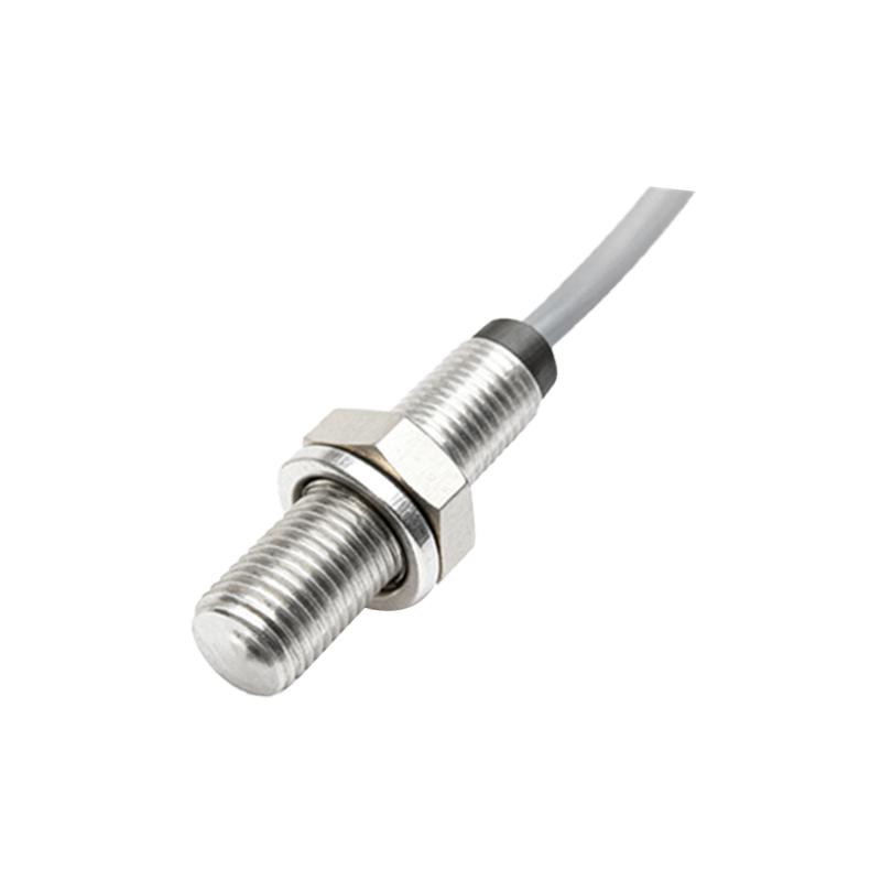
The core electronic circuit is designed to detect this precise change. A stable high-frequency oscillator, often in the range of 100 kHz to 5 MHz, drives the sensor coil. The oscillator's output is then fed into a demodulation and signal conditioning stage. This stage rectifies and filters the high-frequency signal to extract a clean, analog DC voltage that is directly proportional to the distance between the sensor and the target. For digital output types, this analog signal is compared against a preset threshold by a comparator circuit, providing a crisp ON/OFF switch signal.
A significant advantage of the eddy current principle is its sensitivity exclusively to conductive materials. The sensor's performance is influenced by the target's electrical conductivity and magnetic permeability. For instance, ferromagnetic materials like steel produce a stronger effect than non-ferromagnetic metals like aluminum or copper for a given distance, which often requires calibration for the specific target material. The circuit may include compensation or calibration adjustments to account for these material properties and ensure consistent performance.
The design of the sensor coil and the associated circuit is paramount. The coil is usually wound as a flat, shielded design to produce a concentrated magnetic field and minimize external electromagnetic interference. Shielding also helps create a more precise sensing field, resulting in a sharper switching characteristic or more linear analog output. The oscillator circuit must be designed for high stability, as temperature drift or component aging could be misinterpreted as a distance change. Advanced designs incorporate temperature compensation circuits to mitigate this effect.
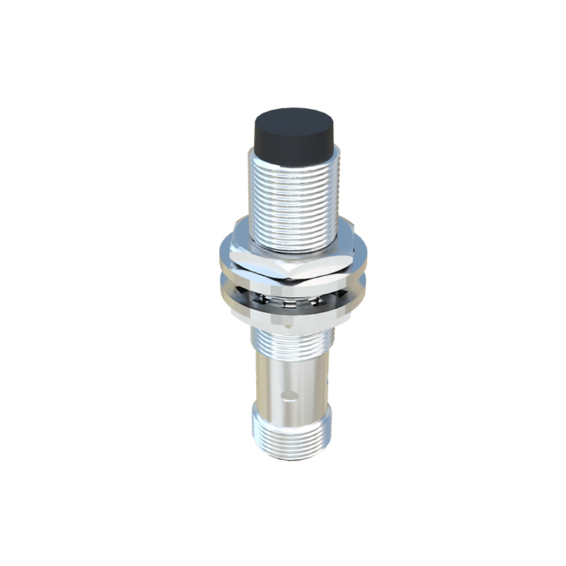
Typical applications are diverse. They are used for precise position measurement of rotating shafts, vibration monitoring in turbines, wear detection in machinery, and as non-contact limit switches in harsh environments where physical contact is undesirable. Their robustness stems from the fact that the sensing element is a simple coil with no moving parts, making them highly reliable and capable of operating in extreme temperatures, pressures, and dirty conditions where optical sensors might fail.
In summary, the efficacy of an eddy current proximity sensor hinges on the sophisticated interplay between its electromagnetic probe and the supporting electronic circuitry. The circuit's role is to generate a stable high-frequency field, sensitively detect minute impedance changes in the coil, and convert these changes into a usable electrical output. This technology offers a unique solution for reliable, long-life sensing of conductive objects without physical contact, forming an indispensable component in modern industrial systems.