Proximity sensors are fundamental components in modern industrial automation, providing non-contact detection of metallic or, in some cases, non-metallic objects. Correct wiring is paramount for ensuring reliable operation, safety, and longevity of both the sensor and the connected control system. This guide details standard wiring methods, supported by conceptual diagrams, for the most common types: 2-wire, 3-wire (NPN and PNP), and 4-wire DC sensors, along with AC models.
Understanding the core specifications is the first step. Always consult the sensor's datasheet for its operating voltage (commonly 10-30V DC or 90-250V AC), output type (NPN sinking, PNP sourcing, or relay), and current rating. The wiring colors, while often standardized (Brown for +V, Blue for 0V/Common, Black for output signal, White for output or complementary signal), can vary by manufacturer.
1. 2-Wire DC/AC Proximity Sensors
These sensors are wired in series with the load, similar to a mechanical switch. They are simple but have a residual voltage drop when "on" and a small leakage current when "off." For DC models, polarity must be observed. Connect one wire to the positive supply and the other to the load, which then connects to the supply negative. For AC models, connect one wire to the Line (Hot) and the other to the load, which then connects to the Neutral. A protective fuse and shielding are recommended for all circuits.
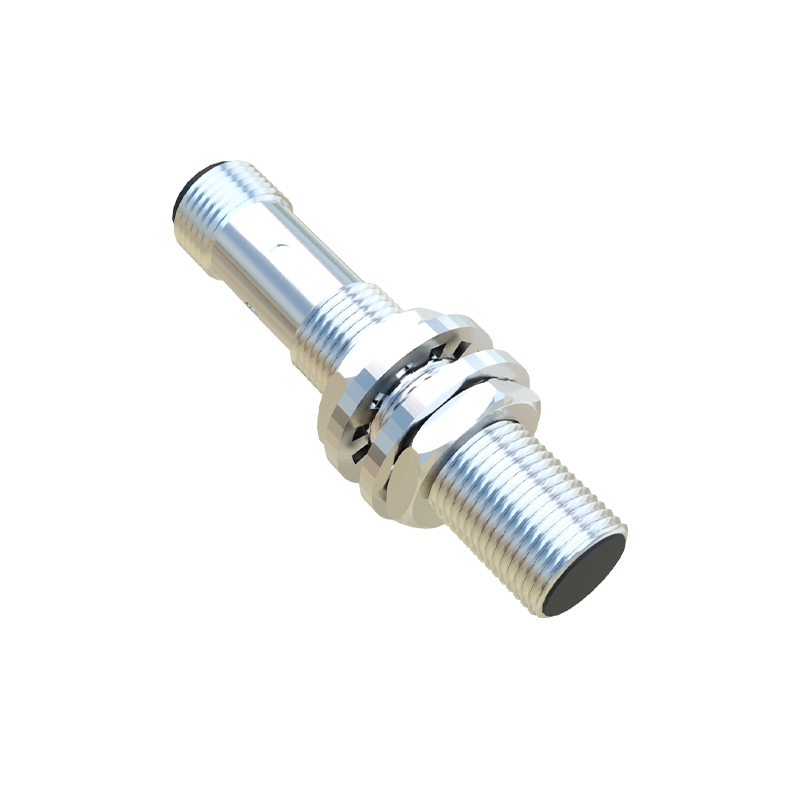
2. 3-Wire DC Proximity Sensors (NPN and PNP)
This is the most prevalent configuration in PLC systems due to superior performance. They have three distinct wires: Brown (+V), Blue (0V), and Black (Output Signal).
PNP (Sourcing) Output: The output switch is connected between the +V supply and the output wire. When activated, the sensor sources current to the load. Wiring: Brown to +V, Blue to 0V, Black to the load. The other side of the load is connected to 0V. The load (e.g., PLC digital input) receives positive voltage when the sensor is triggered.
NPN (Sinking) Output: The output switch is connected between the output wire and the 0V supply. When activated, the sensor sinks current from the load. Wiring: Brown to +V, Blue to 0V, Black to the load. The other side of the load is connected to +V. The load provides a path to positive voltage, which the sensor sinks to 0V when triggered, creating a logic low signal at the PLC input.
3. 4-Wire DC Sensors (Dual Output)
These combine one PNP (Normally Open) and one NPN (Normally Closed) output in a single housing, or provide two complementary outputs (e.g., NO and NC). They typically have Brown (+V), Blue (0V), Black (Output 1), and White (Output 2) wires. The wiring follows the same principles as 3-wire sensors, but allows for more complex control logic, such as enabling a safety check or controlling two different devices based on one sensing event.
4. AC Proximity Sensors
Typically 2-wire or 3-wire, they operate directly on line voltage. A 3-wire AC sensor will have Brown (Line/L), Blue (Neutral/N), and Black (Output) wires. The output is often a solid-state relay (SSR). The load is connected between the Black output wire and the Neutral line. Proper grounding of the sensor body is crucial for safety and noise immunity.
Key Wiring Practices & Safety:
Power Supply: Use a regulated, stabilized DC power supply for DC sensors. For AC sensors, ensure voltage matches exactly.
Load Compatibility: Never exceed the sensor's maximum switching current. For inductive loads (relays, solenoids), use a protective device like a flyback diode (DC) or an RC snubber (AC) across the load to suppress voltage spikes.
Shielding & Separation: Use shielded cables in electrically noisy environments, grounding the shield at one end only. Route sensor cables away from high-voltage power lines and motor drives.
Polarity: Incorrect polarity will damage DC sensors. Double-check before energizing.
Diagrams: Always refer to the pictorial diagram stamped on the sensor body or in its manual. A typical diagram shows the internal circuitry, terminal designations, and wire color codes.
In summary, successful proximity sensor installation hinges on identifying the sensor type, matching the wiring scheme to the control system's input